PCB TOOLS / Electronics reference
VGA Pinout: DE-15, DDC/EDID and Legacy ID Contacts
Look up analog RGB, synchronization and DDC on the three-row 15-contact VGA connector. Compare legacy monitor-ID functions with DDC2/E-DDC, including auxiliary power at 9, data at 12 and clock at 15.
Quick answer
VGA normally uses a three-row high-density DE-15: 1/2/3 carry analog red/green/blue, 6/7/8 their returns, and 13/14 horizontal/vertical sync. DDC2/E-DDC uses SDA at 12 and SCL at 15, with +5 V auxiliary power at 9. Earlier equipment can use these positions for ID or a mechanical key.
Scope
The 15 source rows match NXP AN10873 Table 3. The legacy column records historical ID functions, not a promise that every device implements four ID bits; the right column is scoped to DDC2/E-DDC. Analog video and digital DDC management are separate functions. DDC reads EDID to describe display capabilities; the contact map does not guarantee a resolution, cable length or converter capability. Functional numbering is not a receptacle mating-face or solder-side drawing.
Reading example
If analog video works but the display identity cannot be read, the DDC2/E-DDC column points to SDA 12, SCL 15, auxiliary power 9 and DDC reference ground 10. Do not treat 12/15 only as old ID bits. Horizontal/vertical sync remains at 13/14, separate from the management channel.
Checked reference tables
| Task | Contacts | Meaning |
|---|---|---|
| Analog RGB video | 1 / 2 / 3 | Corresponding returns are 6/7/8 |
| Separate synchronization | 13 / 14 | Horizontal / vertical sync |
| Read EDID (DDC2) | 12 / 15 | SDA data / SCL clock |
| DDC auxiliary power and reference | 9 / 10 | +5 V / DDC ground; verify device capability |
| E-DDC reserved positions | 4 / 11 | Do not impose legacy ID wiring |
Legacy tables with visible corrections
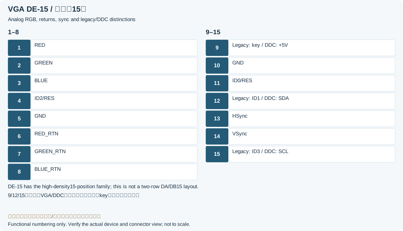
| Pin | Signal | Original VGA | VESA VGA PnP (DDC) |
|---|---|---|---|
| 1 | RED | Red video | Red video |
| 2 | GREEN | Green video | Green video |
| 3 | BLUE | Blue video | Blue video |
| 4 | ID2/RES | Monitor-ID Bit 2 | n.c. - reserved |
| 5 | GND | Ground (HSync) | Ground (HSync) |
| 6 | RED_RTN | Red return | Red return |
| 7 | GREEN_RTN | Green return | Green return |
| 8 | BLUE_RTN | Blue return | Blue return |
| 9 | KEY/PWR | [key] | +5V DC |
| 10 | GND | Ground (VSync, DDC) | Ground (VSync, DDC) |
| 11 | ID0/RES | Monitor-ID Bit 0 | n.c. - reserved |
| 12 | ID1/SDA | Monitor-ID Bit 1 | I²C data |
| 13 | HSync | Horizontal sync | Horizontal sync |
| 14 | VSync | Vertical sync | Vertical sync |
| 15 | ID3/SCL | Monitor-ID Bit 3 | I²C clock |
Frequently asked questions
Why does VGA list both ID bits and SDA/SCL?
The same physical positions have different uses across generations. Contacts 12/15 appear as ID functions in legacy tables and as I²C data/clock in DDC2/E-DDC. Use the column appropriate to the device.
Does EDID travel over the three RGB video lines?
No. DDC2/E-DDC reads EDID through SDA 12 and SCL 15. Analog RGB video uses 1, 2 and 3.
Does a missing contact 9 always indicate damage?
Not necessarily. Early VGA could use the position as a key, whereas DDC equipment may require auxiliary power there. Check the cable/device generation and manufacturer’s connector specification.
Related tools and references
Sources and verification
- NXP: AN10873 section 3.2.10 and Table 3, DE-15/DDC2/E-DDC
- Dell: C5518QT user guide, VGA assignments and EDID plug-and-play
Legacy baseline: the Electrodoc Pro 5.2 data package. Raw records are retained and checked factual corrections are shown explicitly.