PCB TOOLS / PINOUT & INTERFACE REFERENCE
ATX Power Pinout: 24-Pin Main, CPU and PCIe
Identify motherboard-side ATX main power, legacy auxiliary, CPU 4/8-pin and PCIe 6/8-pin functions, separating supply rails, controls and obsolete contacts.
Quick answer
On the 24-pin ATX main connector, contact 8 is PWR_OK, 9 is +5VSB and 16 is active-low PS_ON#. Contact 20 is reserved NC in the modern reference, not a −5 V output. CPU EPS and PCIe eight-pin assignments are different and are not interchangeable.
Scope
The tables cover load-side multi-rail ATX connections with legacy auxiliary and tolerance references. They do not define proprietary PSU-side modular sockets, ATX12VO or 12V-2x6. Historical tolerances are not acceptance criteria for every present-day PSU.
Reading example
Locate +5VSB on main contact 9, not contact 8 PWR_OK. +5VSB can remain present while PS_ON# leaves the main rails off. Read contact 20 as NC; the historical −5 V/white-wire source entry has a visible correction record.
Interfaces, pinouts and technical reference
24-pin ATX12V 2.x
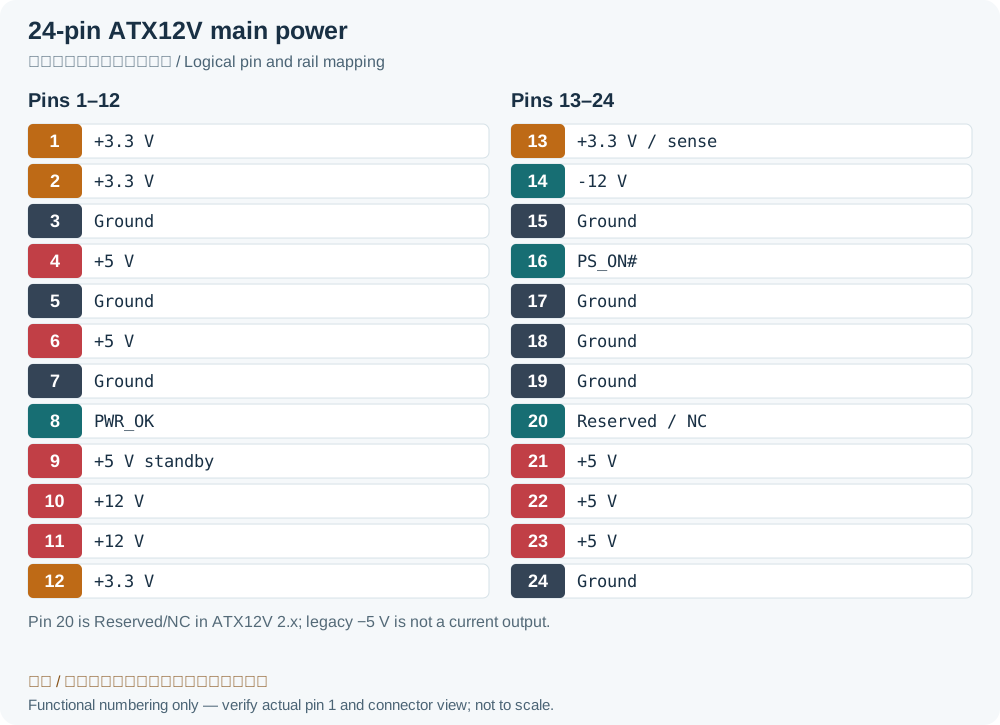
| Color | Signal | Pin | Pin | Signal | Color | |
|---|---|---|---|---|---|---|
| Orange | +3.3 V | 1 | 13 | +3.3 V | Orange | |
| +3.3 V sense | Brown | |||||
| Orange | +3.3 V | 2 | 14 | -12 V | Blue | |
| Black | Ground | 3 | 15 | Ground | Black | |
| Red | +5 V | 4 | 16 | Power on | Green | |
| Black | Ground | 5 | 17 | Ground | Black | |
| Red | +5 V | 6 | 18 | Ground | Black | |
| Black | Ground | 7 | 19 | Ground | Black | |
| Grey | Power good | 8 | 20 | NC (reserved, no connection)Legacy record: “-5V”. Intel Table 4-1 defines main contact 20 as Reserved/NC. The source’s −5 V is an obsolete historical assignment, not a modern output. | No wire (NC)Legacy record: “White”. The modern NC assignment does not retain the historical white −5 V wire. Color is only a reference and does not define modular PSU-side wiring. | |
| Purple | +5 V standby | 9 | 21 | +5 V | Red | |
| Yellow | +12 V | 10 | 22 | +5 V | Red | |
| Yellow | +12 V | 11 | 23 | +5 V | Red | |
| Orange | +3.3 V | 12 | 24 | Ground | Black |
ATX Aux Power Cable
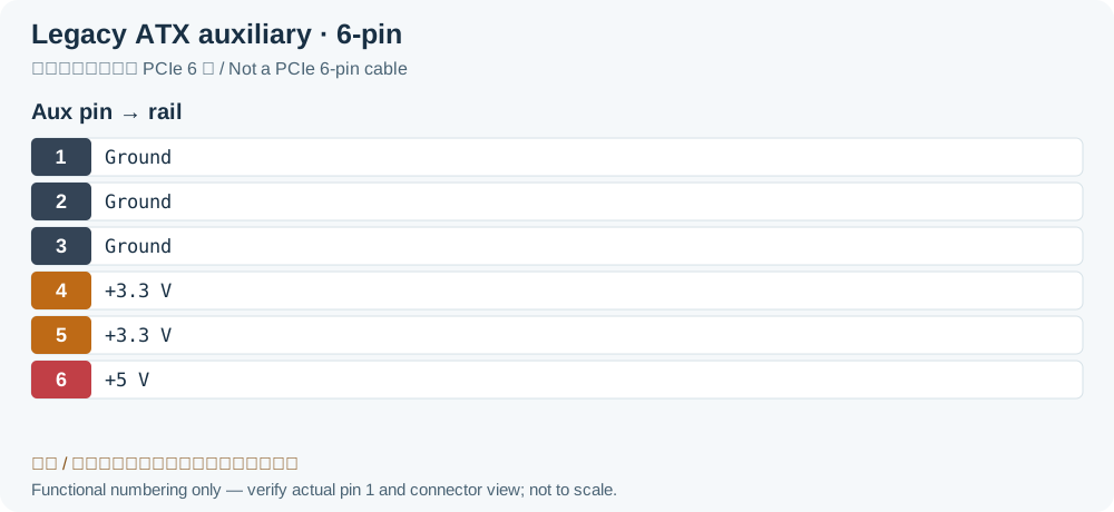
| Pin | Color | Function |
|---|---|---|
| 1 | Black | Ground |
| 2 | Black | Ground |
| 3 | Black | Ground |
| 4 | Orange | +3.3 V |
| 5 | Orange | +3.3 V |
| 6 | Red | +5 V |
ATX 4pin +12V Power Cable
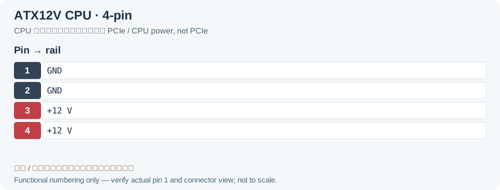
| Color | Function | Pin | Pin | Function | Color | |
|---|---|---|---|---|---|---|
| Black | Ground | 1 | 3 | +12 V | Yellow | |
| Black | Ground | 2 | 4 | +12 V | Yellow |
ATX 8pin EPS +12V Power Cable
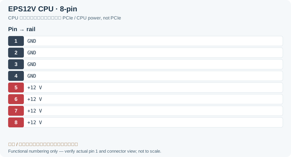
| Color | Function | Pin | Pin | Function | Color | |
|---|---|---|---|---|---|---|
| Black | Ground | 1 | 5 | +12 V | Yellow | |
| Black | Ground | 2 | 6 | +12 V | Yellow | |
| Black | Ground | 3 | 7 | +12 V | Yellow | |
| Black | Ground | 4 | 8 | +12 V | Yellow |
6/8pin PCI Express Power Cable
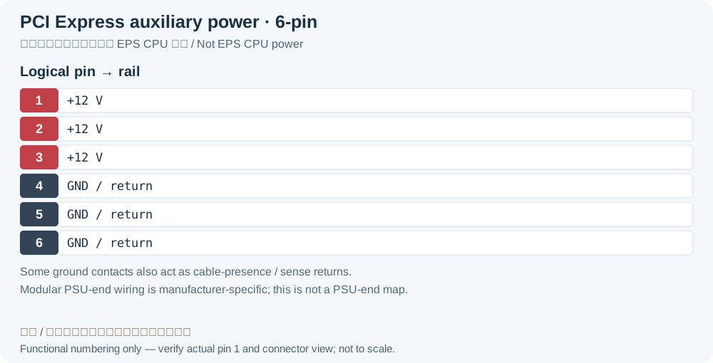
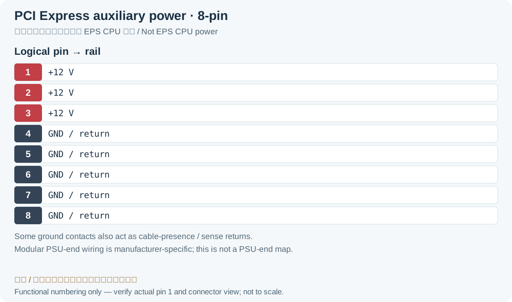
| Color | Function | Pin | Pin | Function | Color | |
|---|---|---|---|---|---|---|
| Yellow | +12 V | 1 | 5 | Ground | Black | |
| Yellow | +12 V | 2 | 6 | Ground | Black | |
| Yellow | +12 V | 3 | 7 | Ground | Black | |
| Black | Ground | 4 | 8 | Ground | Black |
ATX Tolerance
| Volt | Tolerance | Range | Ripple max |
|---|---|---|---|
| +5 V_DC | ±5% (±0.25 V) | +4.75 V to +5.25 V | 50 mV |
| -5 V_DC (obsolete, historical only)Legacy record: “-5 V_DC”. This row preserves the obsolete −5 V rail tolerance for historical reference; it does not apply to modern contact 20 NC. | ±10% (±0.50 V) | -4.50 V to -5.50 V | 50 mV |
| +12 V_DC | ±5% (±0.60 V) | +11.40 V to +12.60 V | 120 mV |
| -12 V_DC | ±10% (±1.2 V) | -10.8 V to -13.2 V | 120 mV |
| +3.3 V_DC | ±5% (±0.165 V) | +3.135 V to +3.465 V | 50 mV |
| +5 V_SB | ±5% (±0.25 V) | +4.75 V to +5.25 V | 50 mV |
Legacy source notes and applicability
These notes retain the legacy record. For corrected facts and applicability, use this page’s quick answer, scope and visible table corrections.
20-pin ATX connector omits the last four pin: 11, 12, 23, 24)
Pins 8, 13, and 16 are control signals:
- "Power On" is pulled up to +5V by the PSU, and must be driven low to turn on the PSU.
- "Power good" is low when other outputs have not yet reached, or are about to leave, correct voltages.
- "+3.3 V sense" line is for remote sensing of the voltage drop in the power supply wiring (should be connected to the +3.3 V on the motherboard)
"+5 V standby" supplies power even when the rest of the supply lines are off.
Pin 20 (-5V, white) is absent in current power supplies; it was optional in ATX and ATX12V ver. 1.2, and deleted as of ver. 1.3.
ATX Aux Power Cable
ATX 4pin +12V Power Cable
ATX 8pin EPS +12V Power Cable
You can plug an 8pin EPS cable into a 4pin 12V motherboard.
You also can plug a 4pin 12V power cable into an 8pin EPS motherboard connector but there's no guarantee that it will work.
6/8pin PCI Express Power Cable
6 pin connector maximum wattage delivery: 75 Watt
8 pin connector maximum wattage delivery: 150 Watt
ATX Tolerance
Frequently asked questions
Is an unpopulated contact 20 necessarily a missing wire?
No. Intel’s main connector assignment defines contact 20 as Reserved/NC. Do not add an old −5 V connection to a modern PSU on that basis.
Are +3.3 V sense and PWR_OK ordinary power outputs?
They serve different functions: the sense connection at 13 supports cable-drop compensation, while PWR_OK at 8 reports supply status. Do not treat control/sense wiring as general load supply rails.
Related tools and references
Sources and verification
Legacy baseline: the Electrodoc Pro 5.2 data package. Raw records are retained and checked factual corrections are shown explicitly.