PCB TOOLS / Electronics reference
DVI Pinout: DVI-I/D/A, Single/Dual Link and Mini-DVI
Look up the complete DVI-I contact map, DVI-D/DVI-A variants and single/dual-link differences, with a separate legacy Apple 32-contact Mini-DVI table. Distinguish analog contacts, the second link, EDID auxiliary power and adapter detection.
Quick answer
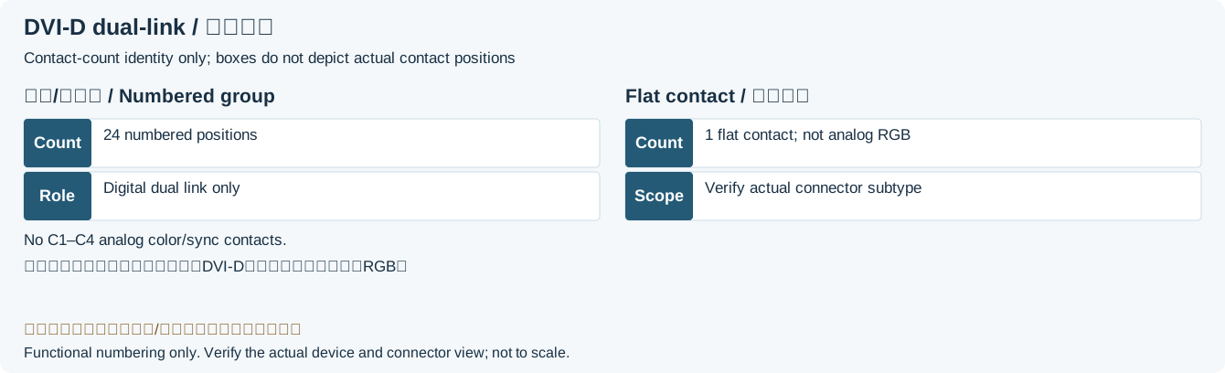
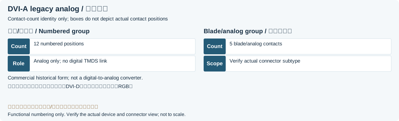
DVI-D is digital only, DVI-I accommodates digital and analog, and DVI-A is analog only. Common plug designations are DVI-D 18+1 single-link / 24+1 dual-link, DVI-I 18+5 single-link / 24+5 dual-link, and DVI-A 12+5. The complete 29-entry DVI-I table does not mean every DVI variant fits all contacts. Mini-DVI is a separate legacy 32-contact interface.
Scope
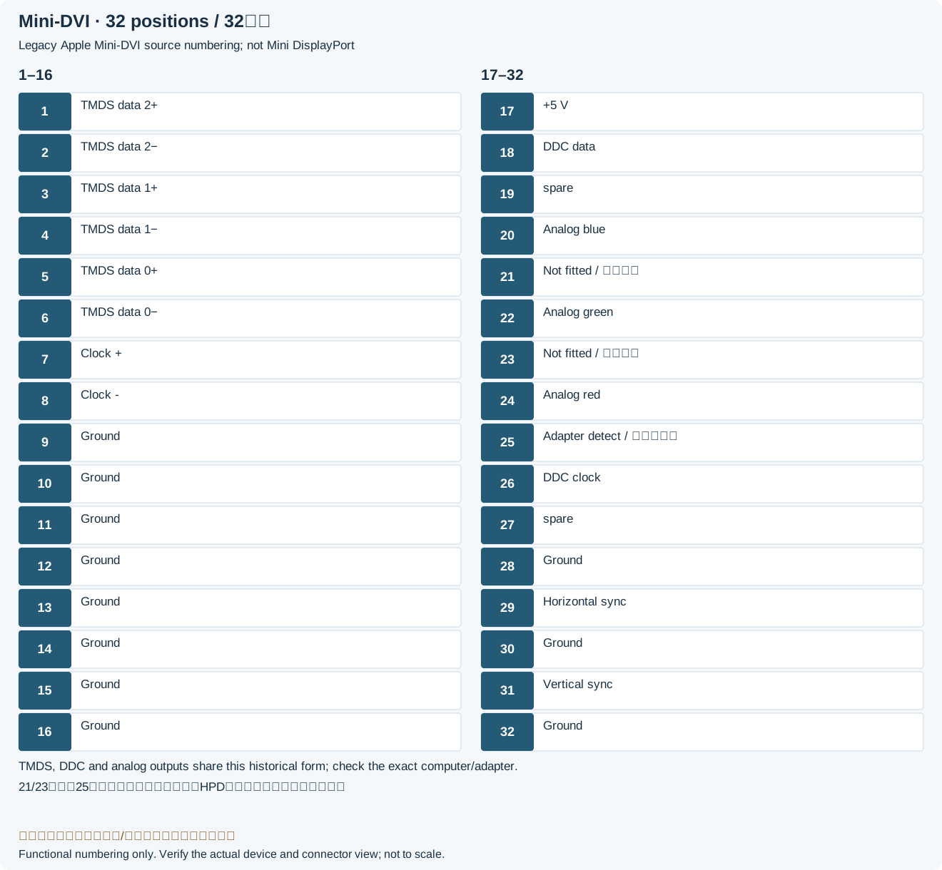
Read the first table as the DDWG DVI 1.0 combined analog/digital interface, and the second as the 2004 12-inch PowerBook G4 Mini-DVI mapping. Single/dual link counts TMDS digital links, not analog plus digital. The usual “+1” mechanically counts the flat contact; it does not give DVI-D analog RGB. DDWG assigns contact 8 as no-connect on DVI-D and analog vertical sync on DVI-I. Functional/population diagrams are not directed installation drawings for mating or solder faces.
Reading example
Dual-link DVI adds data pairs 4/5, 12/13 and 20/21; it shares clock pair 23/24. For a VGA analog display, establish an actual DVI-I or DVI-A analog source: C1/C2/C3 carry RGB, C4 horizontal sync and 8 vertical sync. A passive connector change cannot create these signals from DVI-D-only output.
Checked reference tables
| Variant | Common contact designation | Signals |
|---|---|---|
| DVI-I single-link | 18+5 = 23 | Digital TMDS and analog RGB |
| DVI-I dual-link | 24+5 = 29 | Adds a second digital link; accommodates analog |
| DVI-D single-link | 18+1 = 19 | Digital only; no analog RGB |
| DVI-D dual-link | 24+1 = 25 | Digital only; adds a second digital link |
| DVI-A | 12+5 = 17 | Analog only; no digital dual-link function |
| Mini-DVI | 32 positions (legacy definition) | Separate numbering; legacy Apple model/adapter scope |
Legacy tables with visible corrections
Digital Visual Interface
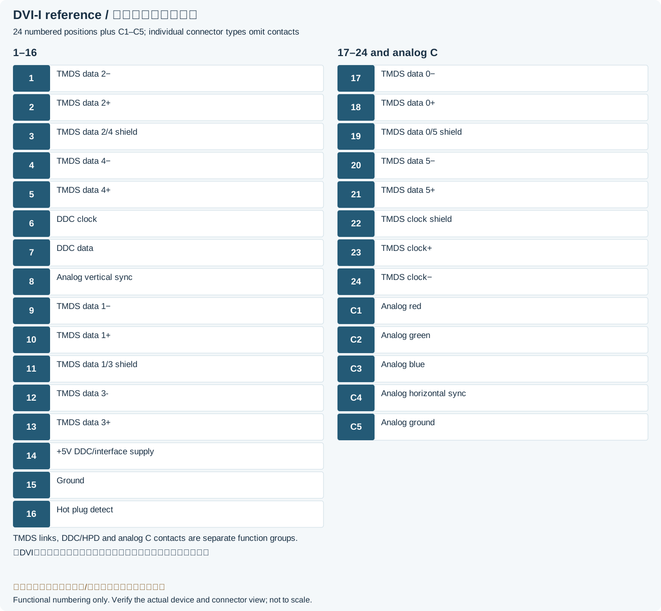
| Pin | Function | Description |
|---|---|---|
| 1 | TMDS data 2− | Digital red− (link 1) |
| 2 | TMDS data 2+ | Digital red+ (link 1) |
| 3 | TMDS data 2/4 shield | |
| 4 | TMDS data 4− | Digital green− (link 2) |
| 5 | TMDS data 4+ | Digital green+ (link 2) |
| 6 | DDC clock | |
| 7 | DDC data | |
| 8 | Analog vertical sync | |
| 9 | TMDS data 1− | Digital green− (link 1) |
| 10 | TMDS data 1+ | Digital green+ (link 1) |
| 11 | TMDS data 1/3 shield | |
| 12 | TMDS data 3- | Digital blue− (link 2) |
| 13 | TMDS data 3+ | Digital blue+ (link 2) |
| 14 | +5 V | DDC auxiliary +5 V: keeps EDID available when main display circuitry is offLegacy record: “Power for monitor when in standby”. DDWG section 2.2.6 and its signal list define EDID availability, not a whole-monitor standby power rating. |
| 15 | Ground | Return for pin 14 and analog sync |
| 16 | Hot plug detect | |
| 17 | TMDS data 0− | Digital blue− (link 1) and digital sync |
| 18 | TMDS data 0+ | Digital blue+ (link 1) and digital sync |
| 19 | TMDS data 0/5 shield | |
| 20 | TMDS data 5− | Digital red− (link 2) |
| 21 | TMDS data 5+ | Digital red+ (link 2) |
| 22 | TMDS clock shield | |
| 23 | TMDS clock+ | Digital clock+ (links 1-2) |
| 24 | TMDS clock− | Digital clock− (links 1-2) |
| C1 | Analog red | |
| C2 | Analog green | |
| C3 | Analog blue | |
| C4 | Analog horizontal sync | |
| C5 | Analog ground | Return for analog signals |
Male DVI connector types
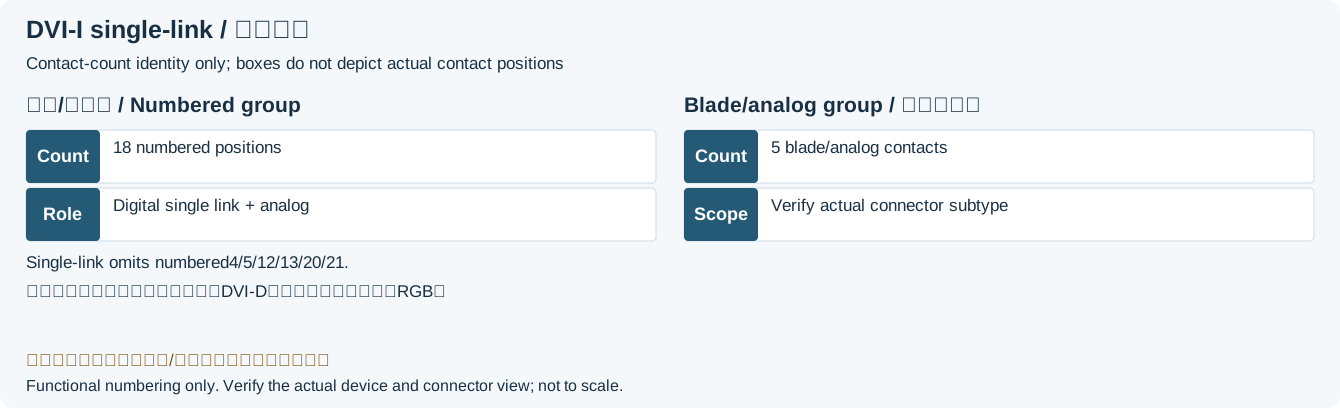
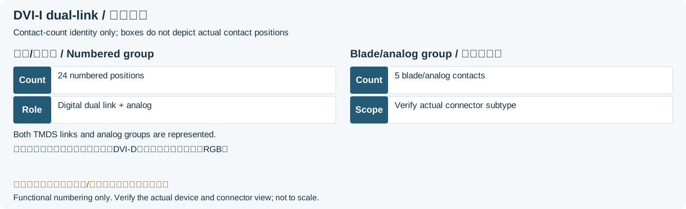
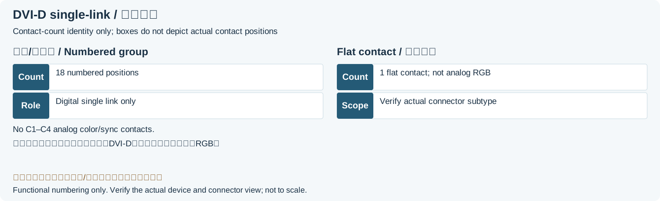
Mini-DVI
| Pin | Signal | Pin | Signal |
|---|---|---|---|
| 1 | TMDS data 2+ | 2 | TMDS data 2− |
| 3 | TMDS data 1+ | 4 | TMDS data 1− |
| 5 | TMDS data 0+ | 6 | TMDS data 0− |
| 7 | Clock + | 8 | Clock - |
| 9 | Ground | 10 | Ground |
| 11 | Ground | 12 | Ground |
| 13 | Ground | 14 | Ground |
| 15 | Ground | 16 | Ground |
| 17 | +5 V | 18 | DDC data |
| 19 | spare | 20 | Analog blue |
| 21 | Not installed in this legacy Apple configurationLegacy record: “n.c.”. Apple Table 3-13 says not installed at position 21, more specific than source n.c.; this does not generalize to all devices. | 22 | Analog green |
| 23 | Not installed in this legacy Apple configurationLegacy record: “n.c.”. Apple Table 3-13 marks position 23 not installed. Preserve the position number without assuming a fitted contact. | 24 | Analog red |
| 25 | Adapter detect (this legacy Apple model)Legacy record: “Hot plug detect”. Apple describes Mini-DVI 25 as tied to +5 V in the adapter for adapter detection, distinct from full-size DVI 16 display HPD. | 26 | DDC clock |
| 27 | spare | 28 | Ground |
| 29 | Horizontal sync | 30 | Ground |
| 31 | Vertical sync | 32 | Ground |
Legacy source notes and applicability
These notes retain the legacy record. For corrected facts and applicability, use this page’s quick answer, scope and visible table corrections.
Male DVI connector types
DVI-I Single Link (digital and analog)
DVI-I Dual Link (digital and analog)
DVI-D Single Link (digital only)
DVI-D Dual Link (digital only)
DVI-A (analog only)
Mini-DVI
Female mini-DVI socket
Frequently asked questions
Can DVI-D drive VGA through a passive adapter?
DVI-D does not provide analog RGB, and a passive connector change cannot convert it. Even DVI-I/DVI-A must actually supply analog output. A digital-only source needs an appropriate active converter.
Does dual-link DVI mean two independent monitors?
No. Two TMDS data links cooperate on one video stream, adding channels while sharing a clock pair. Verify both endpoints and the cable for the target mode; contact count does not by itself guarantee a resolution.
Is Mini-DVI contact 25 equivalent to full-size HPD contact 16?
Do not equate them. Full-size DVI contact 16 is display HPD. On the historical Apple Mini-DVI model here, 25 detects an adapter, which Apple documents as tied to +5 V in that adapter. This is not an instruction to short detection contacts on other interfaces.
Related tools and references
Sources and verification
- DDWG: original DVI 1.0 specification, archived mirror, section 2.2.6 and Tables 5-1/5-2
- Texas Instruments: TS3DV416 DVI connector assignments
- MSI: DVI-I/D/A and 18+1, 24+1, 18+5, 24+5, 12+5 contact configurations
- Apple original Developer Note, archived mirror: 2004 PowerBook G4 Mini-DVI Table 3-13
- StarTech: 32-contact single-link Mini-DVI product specification (connector scope)
Legacy baseline: the Electrodoc Pro 5.2 data package. Raw records are retained and checked factual corrections are shown explicitly.