PCB TOOLS / PINOUT & INTERFACE REFERENCE
USB Pinout: Type-A, Type-B, Mini, Micro and Type-C
Look up USB power, ground, differential data and configuration contacts by connector type. Type-C plugs and receptacles are listed separately by contact number and signal.
Quick answer
On standard USB 2.0 A/B, contacts 1, 2, 3 and 4 are power, D−, D+ and GND. On Mini/Micro, contact 4 is the legacy OTG ID and contact 5 is GND. Type-C receptacle A5/B5 are CC1/CC2, so Mini/Micro ID wiring does not apply.
Scope
Covers the source reference’s USB 1.x/2.0 and legacy USB 3.x connectors plus full-featured Type-C assignments. The historical “USB 3.1” heading does not specify the speed, power or features of every USB-C product. Only the original Type-C receptacle diagram on this site has a verified mating-face front view. Other diagrams and the plug matrix show signal/contact-number relationships; consult the connector’s official drawing for mating views, solder-side views and mechanical layout.
Reading example
For Micro-B USB 2.0 ground, use contact 5 GND rather than contact 4 ID. In the Type-C plug numbering row, the rightmost label is A1; its signal is GND. The source confused that contact label with the signal, and the correction is marked.
Interfaces, pinouts and technical reference
Universal Serial Bus
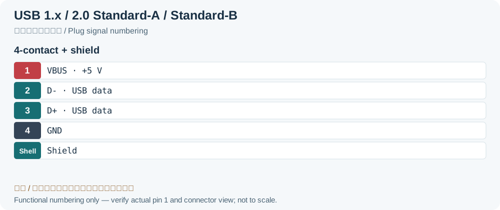
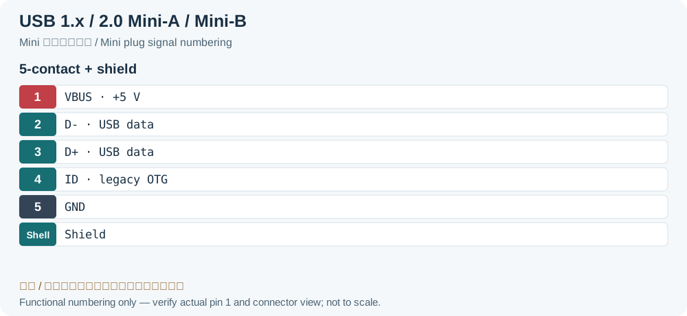
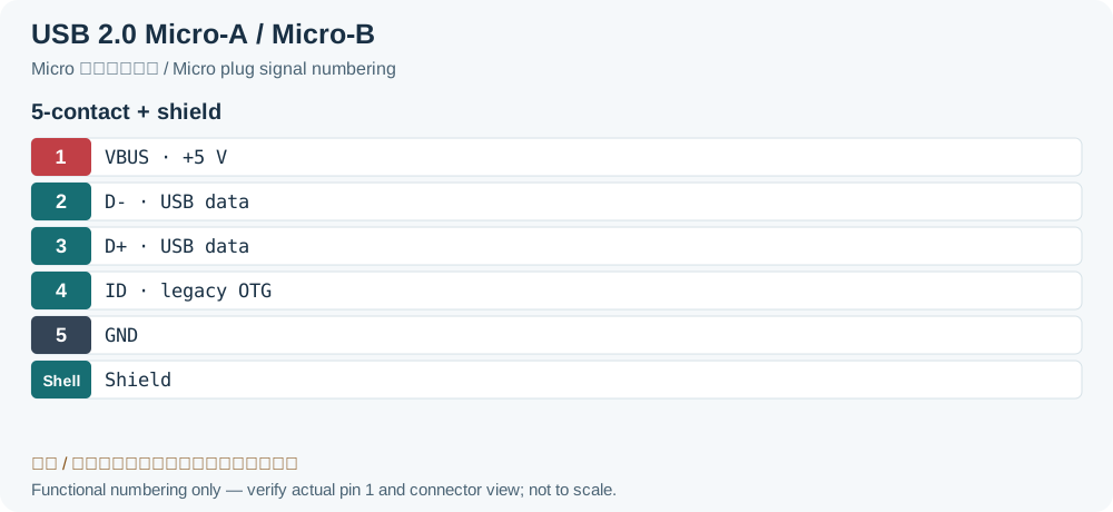
| Pin | Name | Description | Color | |
|---|---|---|---|---|
| Stand. | Mini/Micro | |||
| 1 | 1 | VCC | +5 V | Red |
| 2 | 2 | D- | Data - | White |
| 3 | 3 | D+ | Data + | Green |
| - | 4 | ID | OTG Identification: • host: connected to ground • slave: not connected | Not connected |
| 4 | 5 | GND | Ground | Black |
| Shell | Shield | Metal shell | Drain Wire | |
USB 3.x
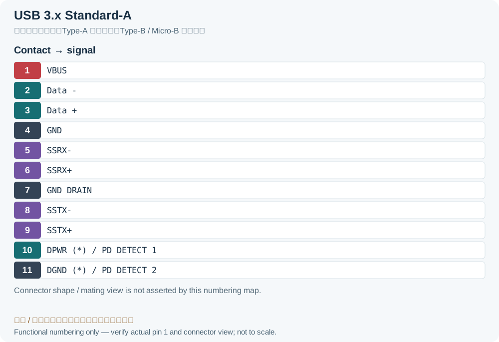
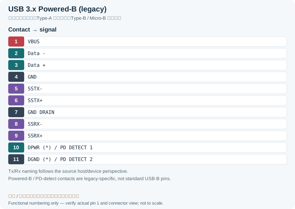
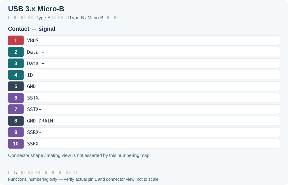
| Pin | Signal | Description | Color (type A) | ||
|---|---|---|---|---|---|
| Type A | Type B (*) | Micro B | |||
| 1 | 1 | 1 | VBUS | Power | Red |
| 2 | 2 | 2 | Data - | USB 2.0 data | White |
| 3 | 3 | 3 | Data + | Green | |
| 4 | 4 | 5 | GND | Ground for power | Black |
| 5 | 8 | 9 | SSRX- | SuperSpeed receiver | Blue |
| 6 | 9 | 10 | SSRX+ | Yellow | |
| 7 | 7 | 8 | GND DRAIN | Ground for signal | |
| 8 | 5 | 6 | SSTX- | SuperSpeed transmitter | Purple |
| 9 | 6 | 7 | SSTX+ | Orange | |
| 10 | 10 | - | DPWR (*) PD DETECT 1 | Power provided by device /PD detect | |
| 11 | 11 | - | DGND (*) PD DETECT 2 | Ground for DPWR /PD detect | |
| - | - | 4 | ID | OTG Identification | |
| Shell | Shield | Connector metal shell | |||
USB 3.1 Type-C
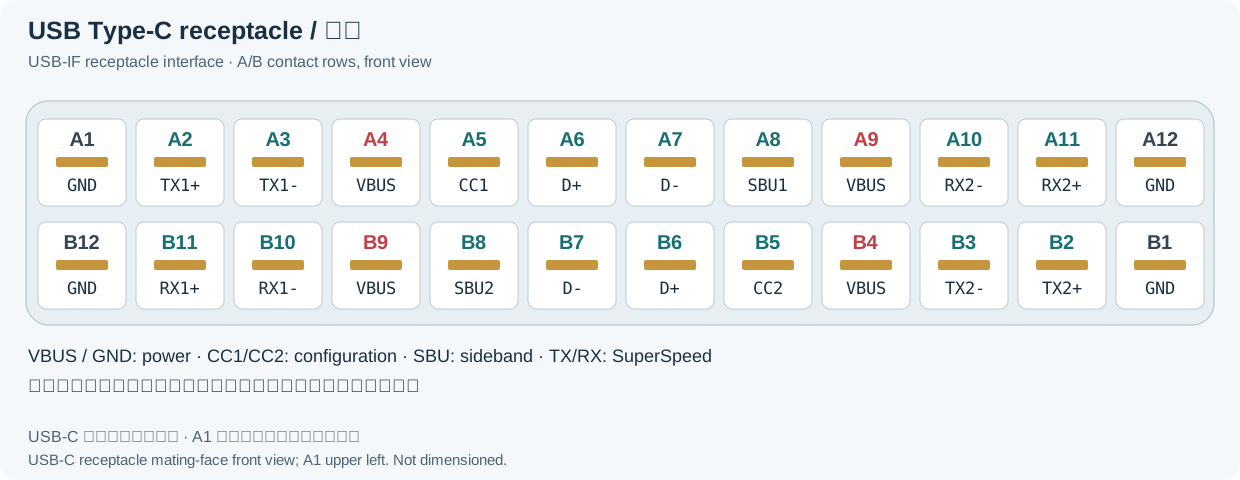
| A1 | A2 | A3 | A4 | A5 | A6 | A7 | A8 | A9 | A10 | A11 | A12 |
|---|---|---|---|---|---|---|---|---|---|---|---|
| GND | TX1+ | TX1- | Vbus | CC1 | D+ | D- | SBU1 | Vbus | RX2- | RX2+ | GND |
| GND | RX1+ | RX1- | Vbus | SBU2 | D- | D+ | CC2 | Vbus | TX2- | TX2+ | GND |
| B12 | B11 | B10 | B9 | B8 | B7 | B6 | B5 | B4 | B3 | B2 | B1 |
| A12 | A11 | A10 | A9 | A8 | A7 | A6 | A5 | A4 | A3 | A2 | A1Legacy record: “GND”. USB-IF Figure 2-2 numbers the plug front view A12 through A1. The source replaced the last contact label with its GND signal; the actual GND signal row is unchanged. |
|---|---|---|---|---|---|---|---|---|---|---|---|
| GND | RX2+ | RX2- | Vbus | SBU1 | D- | D+ | CC | Vbus | TX1- | TX1+ | GND |
| GND | TX2+ | TX2- | Vbus | Vconn | SBU2 | Vbus | RX1- | RX1+ | GND | ||
| B1 | B2 | B3 | B4 | B5 | B6 | B7 | B8 | B9 | B10 | B11 | B12 |
Legacy source notes and applicability
These notes retain the legacy record. For corrected facts and applicability, use this page’s quick answer, scope and visible table corrections.
USB 3.x
Note: Tx and Rx are defined from host perspective for Type-A, and from device perspective for Type-B and Micro-B.
(*) Powered-B USB connector allows USB accessories to draw power from peripheral devices. It is deprecated in USB 3.1 and replaced by Power Delivery (PD) specs.
Pins 10-11 are used in PD receptacle to detect a PD plug.
Standard connectors don't have the pins 10-11.
USB 3.1 Type-C
USB Type-C Receptacle Interface (Front View)
USB Type-C Plug Interface (Front View)
The pin-out is independent of plug orientation.
Connector includes both USB 2.0 (D+ and D-) and USB 3.1 (TX and RX pairs) data buses, USB power (VBUS) and ground (GND), Configuration Channel signals (CC1 and CC2), and two Sideband Use (SBU) signal pins.
Not all signals are required in all platforms or devices.
USB Specifications
- USB Power Specification
- USB Power Delivery Specification
- USB Speed Specification
Related entries from the reference
- USB Power Specification See the official sources below
- USB Power Delivery Specification See the official sources below
- USB Speed Specification See the official sources below
Frequently asked questions
Why does the receptacle show CC1/CC2 but the plug show CC/VCONN?
The receptacle detects attachment and orientation through the active CC contact. A standard Type-C cable carries one through CC path; the other position can supply VCONN to cable electronics. Read the plug and receptacle assignments separately.
Can wire color identify every USB cable?
No. Colors help read the legacy cable reference, but actual cables may differ. Confirm contact numbering, continuity and the manufacturer’s drawing.
Related tools and references
Sources and verification
- USB-IF: Type-C Specification R2.0, Figures 2-1/2-2 and Table 3-4
- USB-IF: Type-C language and capability guidelines
Legacy baseline: the Electrodoc Pro 5.2 data package. Raw records are retained and checked factual corrections are shown explicitly.