PCB TOOLS / Electronics reference
DisplayPort Pinout: Full-Size DP, Mini DP and Pin 20 Power
Look up separate 20-contact source-side mappings for full-size and Mini DisplayPort: Main Link, AUX, HPD, CONFIG and DP_PWR. Distinguish a powered connector contact from an unwired pin 20 in a standard external cable, and from the legacy unexplained 16 V note.
Quick answer
Full-size DP uses AUX+ / AUX− at 15/17 and HPD at 18; Mini DP uses AUX+ / AUX− at 16/18 and HPD at 2. Both use contact 20 for nominal 3.3 V DP_PWR auxiliary power. A standard external DP cable must not wire DP_PWR through between its ends.
Scope
Both original 20-row tables describe external source-side ports. Sink-side lane numbers and differential polarity labels differ; a source-port table is not a sink-port table or cable continuity diagram. Figures show functional numbering. Mini DisplayPort is not Mini-DVI, and DP Alt Mode on USB-C uses different physical contacts. These tables do not establish link speed, UHBR class, DSC or resolution support.
Reading example
For AUX checks, full-size DP uses 15 (+), 17 (−) and 16 (ground); Mini DP uses 16 (+), 18 (−) and 14 (ground). Their HPD contacts are 18 and 2 respectively. On an ordinary DP-to-DP cable, no end-to-end continuity at contact 20 is intentional: the contact can exist without connecting the two auxiliary power outputs.
Checked reference tables
| Function | Full-size DP | Mini DP |
|---|---|---|
| AUX+ | 15 | 16 |
| AUX− | 17 | 18 |
| HPD | 18 | 2 |
| CONFIG1 | 13 | 4 |
| CONFIG2 | 14 | 6 |
| DP_PWR | 20 | 20 |
| Power return | 19 | 19 |
Legacy tables with visible corrections
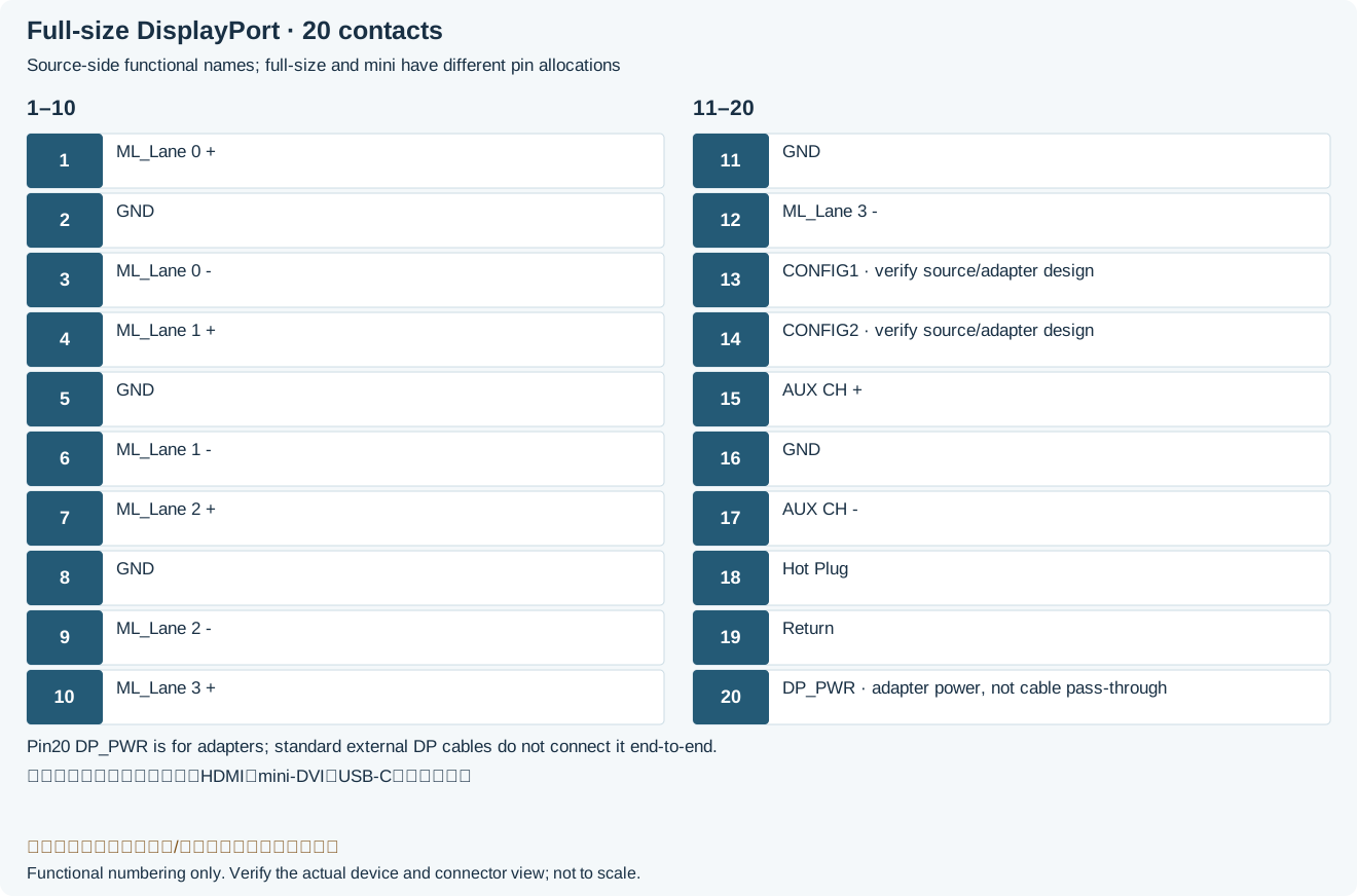
| Pin | Name | Description |
|---|---|---|
| 1 | ML_Lane 0 + | Lane 0 (positive) |
| 2 | GND | Ground |
| 3 | ML_Lane 0 - | Lane 0 (negative) |
| 4 | ML_Lane 1 + | Lane 1 (positive) |
| 5 | GND | Ground |
| 6 | ML_Lane 1 - | Lane 1 (negative) |
| 7 | ML_Lane 2 + | Lane 2 (positive) |
| 8 | GND | Ground |
| 9 | ML_Lane 2 - | Lane 2 (negative) |
| 10 | ML_Lane 3 + | Lane 3 (positive) |
| 11 | GND | Ground |
| 12 | ML_Lane 3 - | Lane 3 (negative) |
| 13 | CONFIG1 | CONFIG1 configuration contact; use port/adapter grounding requirements, not a power groundLegacy record: “connected to Ground”. VESA port tables require pull-downs; the NXP dedicated-adapter example permits direct grounding or a pull-down. The abbreviated source is not a general power-return instruction. |
| 14 | CONFIG2 | CONFIG2 configuration contact; use port/adapter grounding requirements, not a power groundLegacy record: “connected to Ground”. As with CONFIG1, the original wording is not permission for an arbitrary hard power-ground connection. |
| 15 | AUX CH + | Auxiliary Channel (positive) |
| 16 | GND | Ground |
| 17 | AUX CH - | Auxiliary Channel (negative) |
| 18 | Hot Plug | Hot Plug Detect |
| 19 | Return | Return for Power |
| 20 | DP_PWR | DP_PWR: 3.3 V auxiliary power; no through wire on pin 20 of a standard external cableLegacy record: “Power for connector (3.3V 500mA)”. A powered connector contact does not imply a through power conductor; VESA and Dell explicitly distinguish the two. |
Mini DisplayPort
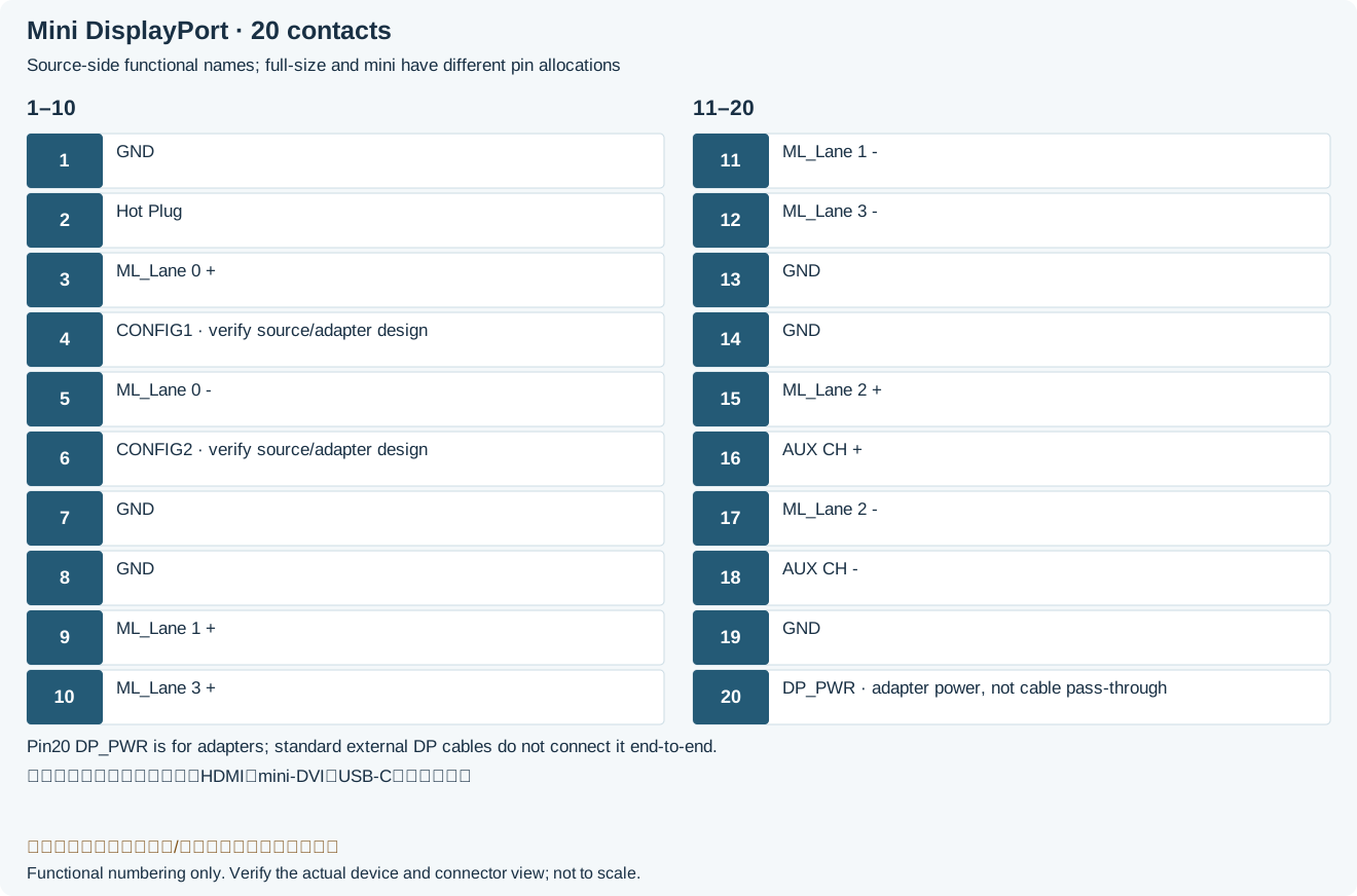
| Pin | Name | Description |
|---|---|---|
| 1 | GND | Ground |
| 2 | Hot Plug | Hot Plug Detect |
| 3 | ML_Lane 0 + | Lane 0 (positive) |
| 4 | CONFIG1 | CONFIG1 configuration contact; grounding follows the port/adapter specificationLegacy record: “CONFIG1”. Mini DP configuration contacts are 4 and 6, not full-size contacts 13 and 14. |
| 5 | ML_Lane 0 - | Lane 0 (negative) |
| 6 | CONFIG2 | CONFIG2 configuration contact; grounding follows the port/adapter specificationLegacy record: “CONFIG2”. Use the VESA Mini DP connector-table conditions; this is not a low-impedance power return. |
| 7 | GND | Ground |
| 8 | GND | Ground |
| 9 | ML_Lane 1 + | Lane 1 (positive) |
| 10 | ML_Lane 3 + | Lane 3 (positive) |
| 11 | ML_Lane 1 - | Lane 1 (negative) |
| 12 | ML_Lane 3 - | Lane 3 (negative) |
| 13 | GND | Ground |
| 14 | GND | Ground |
| 15 | ML_Lane 2 + | Lane 2 (positive) |
| 16 | AUX CH + | Auxiliary Channel (positive) |
| 17 | ML_Lane 2 - | Lane 2 (negative) |
| 18 | AUX CH - | Auxiliary Channel (negative) |
| 19 | GND | Ground |
| 20 | DP_PWR | DP_PWR: 3.3 V auxiliary power; no through wire on pin 20 of a standard external cableLegacy record: “Power for connector”. Mini DP follows the same standard external-cable rule; the original unspecific wording is not an arbitrary supply allowance. |
Legacy source notes and applicability
These notes retain the legacy record. For corrected facts and applicability, use this page’s quick answer, scope and visible table corrections.
Pins 13 and 14 may be connected to ground either directly or through pulldown resistor.
Electrical Signal +3.3V; Max. voltage 16V; Max. current 500mA
Mini DisplayPort
External connector (source-side)
Frequently asked questions
Can full-size and Mini DP be wired number-for-number because both have 20 contacts?
No. HPD is 18 versus 2, and AUX+ is 15 versus 16. Use the signal functions and source/sink definitions, with a compliant cable.
Should contact 20 connect directly to contact 20 at the other end?
Not on an ordinary standard external DP cable. Source and sink may each provide auxiliary power, so a through connection can back-power a device. Dedicated captive cables or adapters must follow their own design and do not redefine ordinary cable wiring.
Why does a monitor manual name a different lane at the same contact number?
Source- and sink-side assignments use different lane and polarity conventions. Establish the endpoint role and the connector’s viewing direction; simply mirroring one figure is not sufficient.
Related tools and references
Sources and verification
- NXP: AN10873 Tables 1/2, full-size/Mini DP source maps and adapter grounding scope
- Wilder: Mini DisplayPort Table 4, source/sink lane names and contact 20
- Dell engineering: unwired cable pin 20 and back-power failures
- VESA: Main Link, AUX, adapters and 3.3 V auxiliary power
- VESA DP 1.2 original specification, archived mirror: Tables 4-4/4-10 and external-cable rules (legacy scope)
- DisplayPort: interface and USB-C Alt Mode distinctions
Legacy baseline: the Electrodoc Pro 5.2 data package. Raw records are retained and checked factual corrections are shown explicitly.