PCB TOOLS / PINOUT & INTERFACE REFERENCE
RS-232 Pinout: DE-9, DB-25 and EIA-561
Find computer-side DTE RS-232 directions, DE-9/DB-25 equivalents and null-modem wiring, with a separate 8P8C serial reference.
Quick answer
A common DE-9 DTE uses contact 2 for RXD input, contact 3 for TXD output and contact 5 for signal ground. Connecting two DTEs requires the appropriate data and handshake crossover; DTE-to-DCE wiring differs.
Scope
Input/output directions are relative to DTE. DE-9 is the nine-contact D-sub shell commonly called DB9; DB-25 is a different size. The 8P8C table shows EIA-561 assignments, not a universal RJ45 console pinout.
Reading example
For two DE-9 DTEs documented for three-wire communication, connect 3 (TXD) to the opposite 2 (RXD), cross the reverse path and join 5 (GND). Hardware flow control additionally requires the relevant handshake wiring.
Interfaces, pinouts and technical reference
RS232
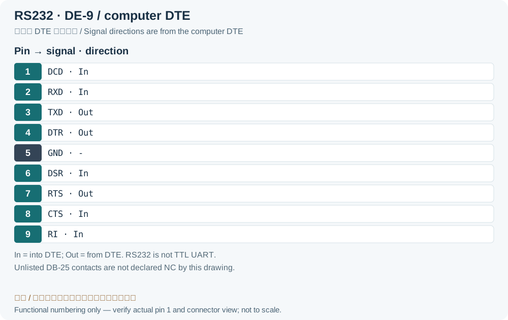
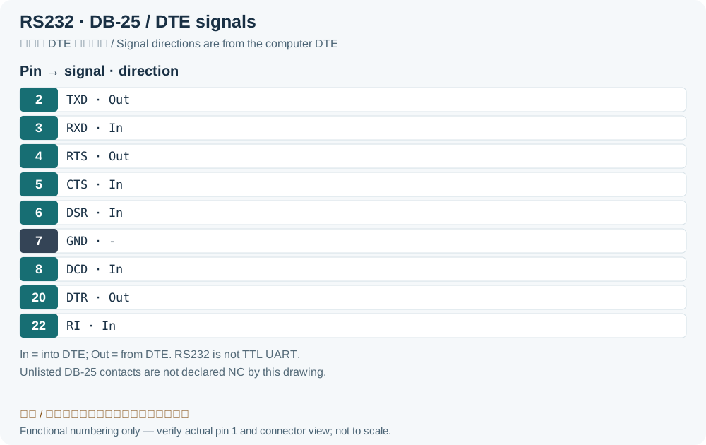
| Pin DE9 | Pin DB25 | Signal | In/Out | Description |
|---|---|---|---|---|
| 1 | 8 | DCD | In | Data Carrier Detect |
| 2 | 3 | RXD | In | Receive Data |
| 3 | 2 | TXD | Out | Transmit Data |
| 4 | 20 | DTR | Out | Data Terminal Ready |
| 5 | 7 | GND | - | Ground |
| 6 | 6 | DSR | In | Data Set Ready |
| 7 | 4 | RTS | Out | Request To Send |
| 8 | 5 | CTS | In | Clear To Send |
| 9 | 22 | RILegacy record: “-RI”. ADI names DE-9 contact 9 / DB-25 contact 22 RI. The source’s hidden formatting dash in “-RI” is not a universal polarity definition. | In | Ring Indicator |
| Shell | Protective Ground | |||
Null modem pin mapping:
| Connector 1 | Connector 2 |
|---|---|
| TxD | RxD |
| RxD | TxD |
| RTS | CTS |
| CTS | RTS |
| GND | GND |
| DSR | DTR |
| DCD | |
| DTR | DSR |
| DCD |
RS232 on RJ45 (EIA-561)
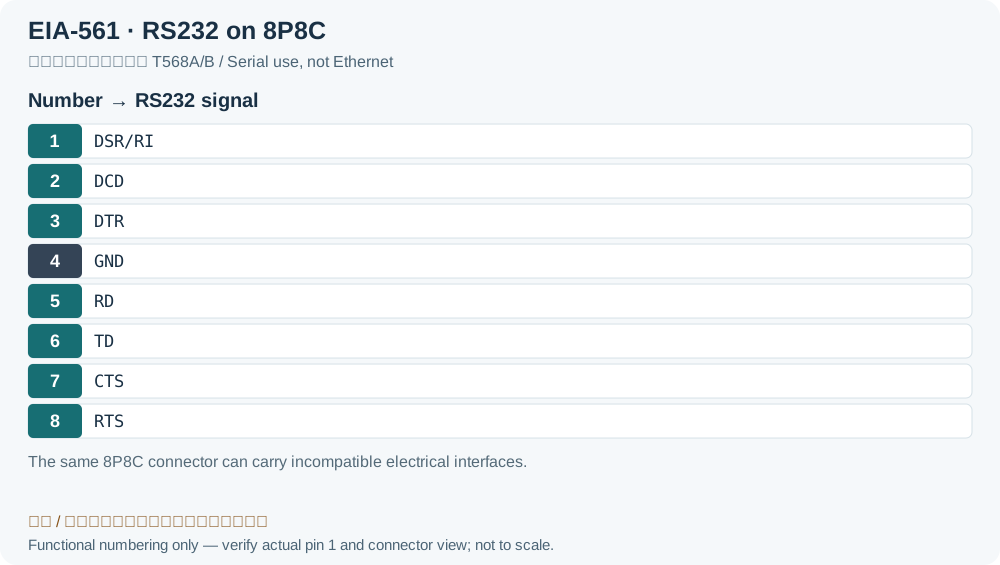
| RJ45 Pin N. | Name | DB9 Cross Connect | Description |
|---|---|---|---|
| 1 | DSR/RI | 6,9 | Data Set Ready/Ring Indicator |
| 2 | DCD | 1 | Data Carrier Detect |
| 3 | DTR | 4 | Data Terminal Ready |
| 4 | GND | 5 | Ground |
| 5 | RD | 2 | Receive Data |
| 6 | TD | 3 | Transmit Data |
| 7 | CTS | 8 | Clear to Send |
| 8 | RTS | 7 | Request to Send |
Legacy source notes and applicability
These notes retain the legacy record. For corrected facts and applicability, use this page’s quick answer, scope and visible table corrections.
(*) Pinout is at DTE (Computer) side
Null modem pin mapping:
RS232 on RJ45 (EIA-561)
8 pin RJ45 male connector (Plug)
Frequently asked questions
Does TXD have the same number on DE-9 and DB-25?
No. DTE TXD is DE-9 contact 3 and DB-25 contact 2; RXD is DE-9 contact 2 and DB-25 contact 3.
Why is EIA-561 contact 1 labeled DSR/RI?
The position can carry the DSR or RI function used by the equipment. “6,9” identifies corresponding DE-9 functions; it is not an instruction to short contacts 6 and 9 on arbitrary hardware.
Related tools and references
Sources and verification
- Analog Devices: RS232 Quick Guide, assignments, directions and electrical characteristics
- TOKYO KEIKI: UW-10 manual, Table 5-2 EIA-561 assignments
Legacy baseline: the Electrodoc Pro 5.2 data package. Raw records are retained and checked factual corrections are shown explicitly.