PCB TOOLS / Electronics reference
XLR and DMX Pinout: Balanced Audio, Phantom Power and 3/5-Pin Differences
Compare three-contact XLR audio, manufacturer three-contact DMX and standard five-contact DMX functions, with contact-number, shield/common and phantom-power limits.
Quick answer
Common balanced XLR audio uses 1 shield, 2 signal high and 3 signal low. Five-contact DMX uses 1 data common, 2 Data1−, 3 Data1+, 4 Data2− and 5 Data2+. Audio and DMX therefore assign different roles to contacts 2/3. P48 phantom places the same +48 V DC on audio contacts 2 and 3 relative to 1, not 48 V between 2 and 3.
Scope
Identify contact numbers from their markings. Male pins, female sockets, mating faces and solder views must not be guessed by mirroring. Site drawings show functional numbering without a universal mechanical orientation. DMX references ANSI E1.11-2024; common manufacturer three-contact implementations are separately scoped, and the unidentified five-contact power table remains historical only.
Reading example
The primary five-contact DMX link uses 2 (Data1−) and 3 (Data1+). In the common source-at-one-end bus, place the 120 Ω far-end termination across 2/3, not 1/2. With P48 audio, both 2 and 3 at +48 V relative to 1 give an ideal DC difference of 48 − 48 = 0 V. This is not the separate +48 V contact in the historical five-contact power table.
Checked reference tables
| Contact | Common balanced audio | Five-contact DMX primary/secondary |
|---|---|---|
| 1 | Cable shield | Data common |
| 2 | Signal high | Data1− |
| 3 | Signal low | Data1+ |
| 4 | — | Optional Data2−, not power |
| 5 | — | Optional Data2+, not power |
Legacy tables with visible corrections
XLR-3
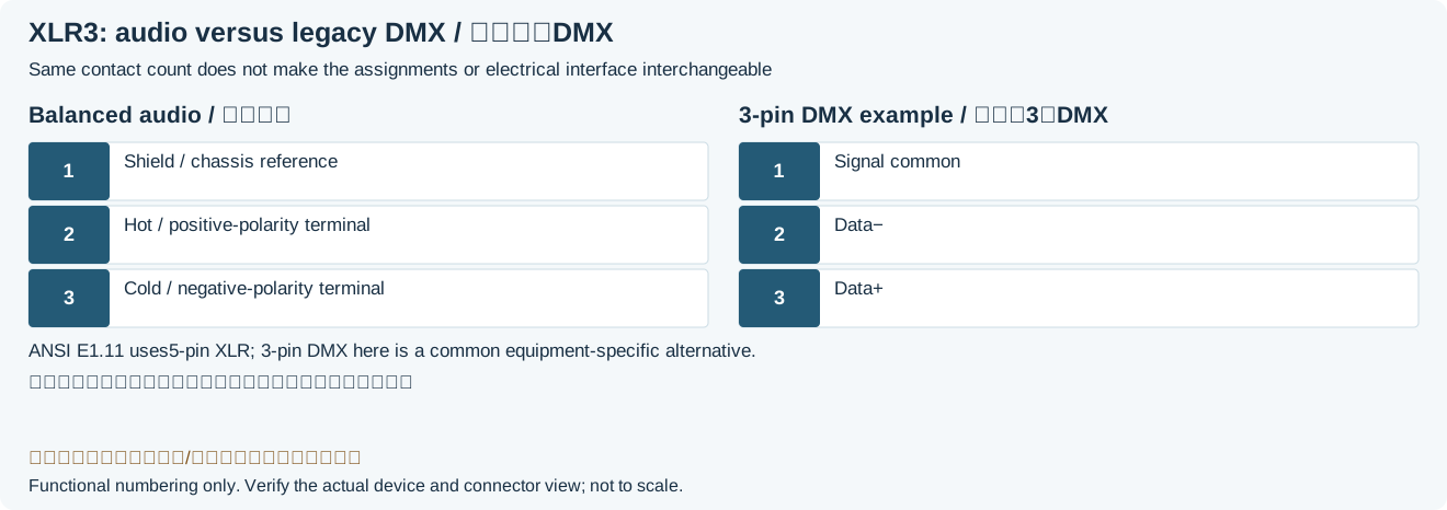
| Pin | XLR-3 Balanced |
|---|---|
| 1 | Chassis Ground (cable shield) |
| 2 | Positive polarity terminal / Phase A / hot |
| 3 | Signal low/cold; not shield or common groundLegacy record: “Return terminal / Phase B / cold”. The source Return/Phase B/cold is the audio low terminal, not a shield return to ground arbitrarily; equal opposite drive is not universal. |
| Pin | XLR-3 Unbalanced |
|---|---|
| 1 | Ground (cable shield) |
| 2 | Signal |
| 3 | Join 1 only for a documented compatible unbalanced adapter; not universalLegacy record: “Ground (connect to pin 1)”. Neutrik NA2FPMF documents 1/3 grounded, but the source gives no equipment/direction; this is not permission to short arbitrary balanced outputs or phantom interfaces. |
| Pin | DMX512 Connector |
|---|---|
| 1 | Signal Common |
| 2 | Data - (Data Link) |
| 3 | Data + (Data Link) |
XLR-5
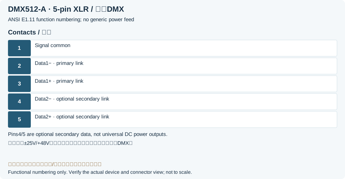
| Pin | DMX512 Connector |
|---|---|
| 1 | Signal Common |
| 2 | Data 1- (Primary Data Link) |
| 3 | Data 1+ (Primary Data Link) |
| 4 | Data 2- (Optional Secondary Data Link) |
| 5 | Data 2+ (Optional Secondary Data Link) |
| Pin | Power Supply Connector |
|---|---|
| 1 | Audio Supply -25V |
| 2 | Phantom Supply +48V |
| 3 | Audio Supply +25V |
| 4 | Audio Ground |
| 5 | Audio Ground |
Legacy source notes and applicability
These notes retain the legacy record. For corrected facts and applicability, use this page’s quick answer, scope and visible table corrections.
XLR-5
Frequently asked questions
Does a three-to-five-contact DMX adapter convert audio too?
No. A compatible adapter only routes DMX data/common contacts. It does not convert audio to DMX, create an absent secondary link or correct unsuitable cable impedance.
Must XLR contact 3 always carry an equal inverted waveform?
No. Balanced operation depends on the signal terminals’ impedance relationship to reference; an impedance-balanced output can drive only one side. Distinguish the low-terminal role from a particular circuit’s waveform, and do not treat it as universal ground.
Can the same left/right front-view positions be used for male and female XLR?
Do not infer geometry from a function table. Use molded contact numbers and the exact model’s mating/solder-view drawing. This functional reference is not a mechanical view to mirror.
Which contacts receive the DMX end termination?
Across primary Data1−/Data1+, contacts 2 and 3 in this five-contact definition. A common source-at-one-end link terminates at the far end. Other topologies require the standard and manufacturer instructions; the terminator is not connected to shield/common instead.
Related tools and references
Sources and verification
- ESTA ANSI E1.11-2024: §4.8/4.9 and §7/Table 3
- ETC: DMX connectors, data cable and 120 Ω termination
- Shure: equal phantom voltage on 2/3 relative to 1
- Neutrik NA2FPMF: a specific unbalanced adapter mapping
- Sound Devices: balanced-output topology and low terminal
Legacy baseline: the Electrodoc Pro 5.2 data package. Raw records are retained and checked factual corrections are shown explicitly.