PCB TOOLS / Electronics reference
Audio Jack Pinout: TS, TRS, TRRS and CTIA/OMTP
Identify mono, stereo, balanced-line and headset connections by audio-plug contact segments. Distinguish 3.5 mm/6.35 mm form, CTIA/OMTP microphone positions and historical A/V arrangements.
Quick answer
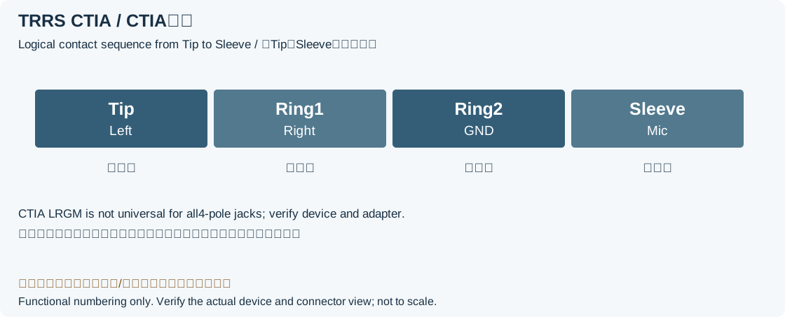
Identify contacts from the plug tip toward the cable as T (Tip), R1, R2 and S (Sleeve). Common stereo TRS uses T left, R right and S common; balanced mono TRS instead uses T signal high, R signal low and S shield. Four-contact CTIA headsets use left/right/ground/microphone; OMTP uses left/right/microphone/ground, swapping the last two segments.
Scope
TS/TRS/TRRS describe contact segments, not signal level, balanced operation or socket compatibility. The source A/V plug drawing labels 1, 2, 3, 4 from tip toward cable as T/R1/R2/S; these are not socket solder-terminal numbers, and the brand table gives no device models. Original drawings show contact-segment or function relationships; socket solder terminals and switching contacts require the exact connector drawing.
Reading example
On the same three-segment TRS form, R is the right channel on a stereo headphone output but the signal-low terminal on a balanced mono input. They are different uses. A CTIA headset has ground at R2 and microphone at S; an OMTP connection needs a verified adapter swapping those segments, not merely a matching four-contact shell.
Checked reference tables
| Use | T | R1 | R2 | S |
|---|---|---|---|---|
| TS unbalanced mono | Signal | — | — | Reference/shield |
| TRS unbalanced stereo | L | R | — | Common |
| TRS balanced mono | Signal high | Signal low | — | Shield |
| TRRS / CTIA | L | R | Ground | Microphone/control |
| TRRS / OMTP | L | R | Microphone | Ground |
Legacy tables with visible corrections
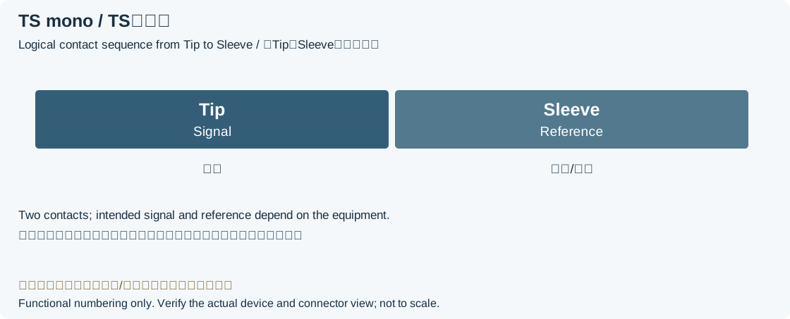
Mono plug (TS)
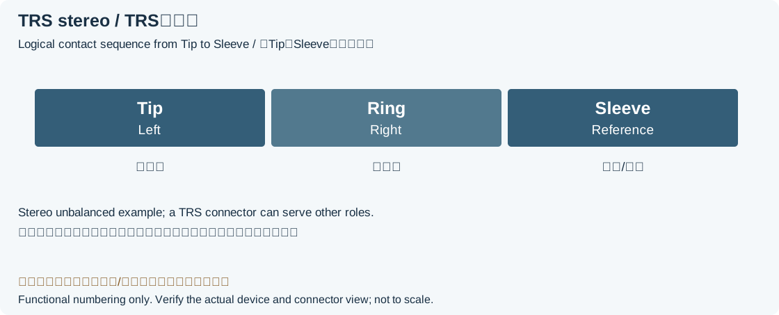
Stereo plug (TRS)
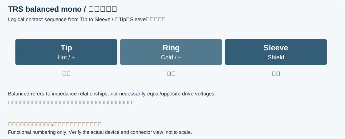
Balanced mono (TRS)
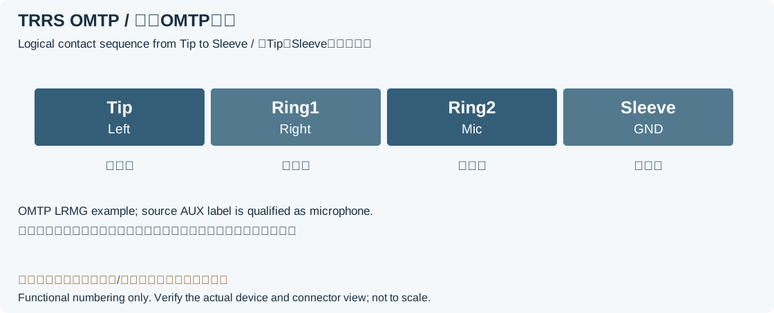
Stereo plug 4-pole
Universal 4-pole cell phone headset
Audio/Video plug 4-pole
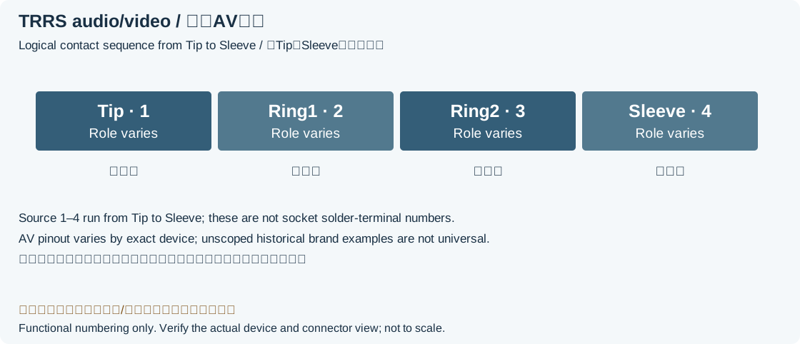
| Pin | Sony | Panasonic | Nokia | Samsung |
|---|---|---|---|---|
| 1 | Left Audio | Right Audio | Left Audio | Left Audio |
| 2 | Composite Video | A&V Ground | Right Audio | Right Audio |
| 3 | A&V Ground | Composite Video | Composite Video | A&V Ground |
| 4 | Right Audio | Left Audio | Ground | Composite Video |
Color Codes (PC99 standard)
| Legacy connector/color description | Legacy function and applicability |
|---|---|
| Green TRS 3.5mm | Stereo output, front channels or headphones |
| Black TRS 3.5mm | Stereo output, rear channels |
| Grey TRS 3.5mm | Stereo output, side channels |
| Center/subwoofer commonly orange; source says Gold, background retainedLegacy record: “Gold TRS 3.5mm”. Dell marks center/subwoofer orange. The source Gold description is not universal; the original term and background are retained for traceability. | Dual output, center and subwoofer |
| Blue TRS 3.5mm | Stereo input, line level |
| Pink TRS 3.5mm | Mono or stereo microphone input |
Legacy source notes and applicability
These notes retain the legacy record. For corrected facts and applicability, use this page’s quick answer, scope and visible table corrections.
SIG = Signal (tip) GND = Ground (sleeve)
Stereo plug (TRS)
L = Left channel (tip) R = Right channel (ring) GND = Ground (sleeve)
Balanced mono (TRS)
+ = Positive phase (tip) - = Negative phase (ring) GND = Ground (sleeve)
Stereo plug 4-pole
L = Left channel (tip) R = Right channel (ring) AUX = Auxiliary signal (ring) GND = Ground (sleeve) Used by Nokia and in some old phones. Other devices use "Universal 4-pole cell phone headset" (AUX and GND are inverted)
Universal 4-pole cell phone headset
L = Left channel (tip) R = Right channel (ring) GND = Ground (ring) MIC = Microphone & Control (sleeve) Used in most cell phones and tablets (HTC, Samsung, Blackberry, Sony, Motorola, iPhone, iPod)
Audio/Video plug 4-pole
Color Codes (PC99 standard)
Frequently asked questions
Does TRS always mean stereo?
No. It can carry unbalanced stereo, balanced mono or a device-specific send/return insert. Identify the port function first; three contacts do not automatically balance a single-ended signal.
Do CTIA and OMTP swap only microphone and ground?
For the basic four-contact layouts listed here, T left and R1 right are unchanged, while microphone/ground swap between R2 and S. Matching those contacts alone does not guarantee every remote button or detection function.
Can the historical A/V brand table be used directly to solder a cable?
Not from a brand name alone. Confirm model, exact segment numbering, signal levels and the original cable definition. The source does not establish all those conditions, so a shared brand does not prove compatibility.
Related tools and references
Sources and verification
- Android: CTIA LRGM and OMTP LRMG
- Yamaha: TS/TRS uses and balanced/unbalanced connections
- Sound Devices: impedance balance without equal opposite drive
- Dell: audio-port functions and orange center/subwoofer marking
- Shure: microphone bias versus phantom power
Legacy baseline: the Electrodoc Pro 5.2 data package. Raw records are retained and checked factual corrections are shown explicitly.