PCB TOOLS / Electronics reference
RCA Connector Uses and Colors: Analog Audio, Video and S/PDIF
Look up common RCA colors and channel/video roles, using port labels first to distinguish analog audio, composite video, YPbPr/RGB and coaxial digital audio.
Quick answer
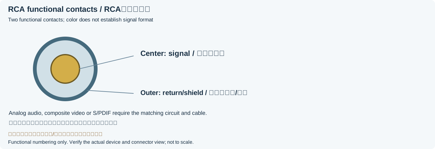
A common RCA connection uses the center contact for signal and the outer contact for reference/shield, but RCA shape and color do not define the electrical protocol. White/red can mark analog left/right, yellow composite video and orange coaxial S/PDIF. Red can also identify Pr or the R channel of RGB.
Scope
The table records historical identification conventions, not guaranteed wiring for every manufacturer, region or product. Analog line, composite/component video and S/PDIF have different level, impedance and encoding requirements. RCA or “Phono” here names the connector, not an automatic input type. The original diagram separates center and outer-contact functions without defining arbitrary power or solder-terminal layouts.
Reading example
Analog audio right, YPbPr Pr and RGB R can all be red. Read “R AUDIO,” “Pr” or “R” before choosing the connection rather than cross-connecting by color. A coaxial S/PDIF example uses a 75 Ω transmission system; this is characteristic impedance, not the cable’s end-to-end DC resistance measured with a multimeter.
Checked reference tables
| Port family | Typical use | Not established by RCA form |
|---|---|---|
| Analog audio L/R | One analog channel per port | S/PDIF digital format |
| Composite video | One composite video signal | Component YPbPr/RGB or HDMI conversion |
| YPbPr / RGB | Multiple components and applicable sync | Compatibility of every red/green/blue port |
| S/PDIF coaxial | Encoded digital audio; select 75 Ω cable for the system | Direct analog compatibility or arbitrary format decoding |
Legacy tables with visible corrections
| Signal family | Channel/component | Legacy color name | Additional legacy swatch (blank text retained) |
|---|---|---|---|
| Composite analog video | Composite | Yellow | |
| Analog audio | Left/Mono | White | |
| Right | Red | ||
| Center | Green | ||
| Left surround | Blue | ||
| Right surround | Gray | ||
| Left back surround | Brown | ||
| Right back surround | Tan | ||
| Subwoofer | Purple | ||
| Digital audio | S/PDIF | Orange | |
| Component analog video (YPbPr) | Y | Green | |
| P_B | Blue | ||
| P_R | Red | ||
| Component analog video/VGA (RGB/HV) | R | Red | |
| G | Green | ||
| B | Blue | ||
| H(Horizontal sync)/S(Composite Sync) | Yellow | ||
| V(Vertical sync) | White |
Frequently asked questions
Are red/white RCA leads a digital stereo connection?
A common red/white pair carries two analog channels, red right and white left/mono. Coaxial S/PDIF normally has an explicit digital-port label. The equipment label governs; shell appearance alone does not.
Does connecting analog RCA to S/PDIF automatically digitize it?
No. Matching connectors do not match encoding or electrical requirements. Use a suitable ADC/DAC or interface converter and verify signal direction and format.
Why cannot a multimeter directly verify a 75 Ω digital cable?
Characteristic impedance arises from distributed inductance and capacitance and describes traveling-wave voltage/current. A DC multimeter measures conductor resistance or continuity, not transmission-line characteristic impedance.
Related tools and references
Sources and verification
- Neutrik: RCA/Phono connector and signal/ground contacts
- Yamaha: RCA and unbalanced analog audio connections
- Yamaha CDR-HD1000 manual: digital-coaxial/analog interfaces and 75 Ω specification
Legacy baseline: the Electrodoc Pro 5.2 data package. Raw records are retained and checked factual corrections are shown explicitly.