PCB TOOLS / Electronics reference
VESA P&D and EVC legacy connector
Compare historical35-position P&D analog/digital and EVC v1 TMDS, analog video, USB, 1394 and auxiliary functions.
Quick answer
VESA here means Plug and Display, not monitor mounting holes or a motherboard feature header.
Scope
Retains source EVC v1/P&D columns and merged cells; EVC v2 changed allocation.Full public normative coverage was unavailable, so this archive does not define a universal powered adapter.
Reading example
At position 11, EVC v1 lists power while P&D lists TMDS Data1+; identify the version first.
Legacy tables with visible corrections
P&D (VESA Plug and Display)
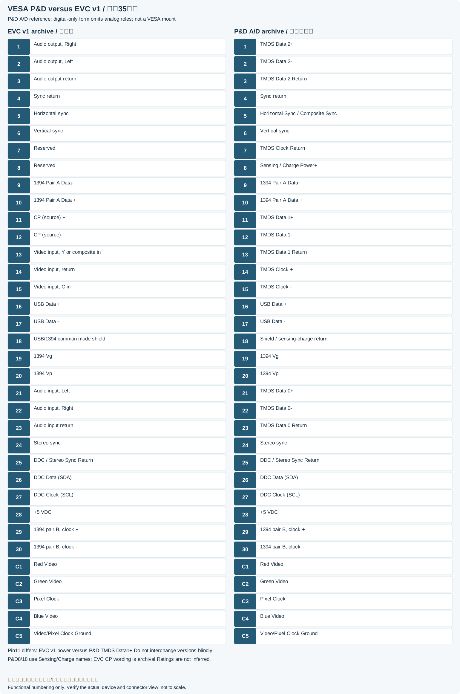
| Pin | EVC v.1 | P&D Analog/Digital | P&D Digital |
|---|---|---|---|
| 1 | Audio output, Right | TMDS Data 2+ | |
| 2 | Audio output, Left | TMDS Data 2- | |
| 3 | Audio output return | TMDS Data 2 Return | |
| 4 | Sync return | - | |
| 5 | Horizontal sync | Horizontal Sync / Composite Sync | - |
| 6 | Vertical sync | - | |
| 7 | Reserved | TMDS Clock Return | |
| 8 | Reserved | Sensing/Charge Power+Legacy record: “Change Power+”. The Molex P&D chart names8 Sensing/Charge Power+; source Change is a wording error, not a voltage rating. | |
| 9 | 1394 Pair A Data- | ||
| 10 | 1394 Pair A Data + | ||
| 11 | Change Power + | TMDS Data 1+ | |
| 12 | Change Power- | TMDS Data 1- | |
| 13 | Video input, Y or composite in | TMDS Data 1 Return | |
| 14 | Video input, return | TMDS Clock + | |
| 15 | Video input, C in | TMDS Clock - | |
| 16 | USB Data + | ||
| 17 | USB Data - | ||
| 18 | USB/1394 common mode shield | 1394 outer shield/Sensing-Charge return(per version/cable)Legacy record: “1394 Outer Shield / Change Power -”. The Molex cable chart lists18 as Sensing/Charge Power return; the source Change spelling/multiple roles need version limits. | |
| 19 | 1394 Vg | ||
| 20 | 1394 Vp | ||
| 21 | Audio input, Left | TMDS Data 0+ | |
| 22 | Audio input, Right | TMDS Data 0- | |
| 23 | Audio input return | TMDS Data 0 Return | |
| 24 | Stereo sync | - | |
| 25 | DDC / Stereo Sync Return | DDC return | |
| 26 | DDC Data (SDA) | ||
| 27 | DDC Clock (SCL) | ||
| 28 | +5 VDC | ||
| 29 | 1394 pair B, clock + | ||
| 30 | 1394 pair B, clock - | ||
| C1 | Red Video | - | |
| C2 | Green Video | - | |
| C3 | Pixel Clock | - | |
| C4 | Blue Video | - | |
| C5 | Video/Pixel Clock Ground | - | |
| Interface group1 | Interface group2 |
|---|---|
| Audio output | Audio input |
| Analog Video | Digital Video |
| DDC Interface | Video input |
| USB | Firewire |
Legacy source notes and applicability
These notes retain the legacy record. For corrected facts and applicability, use this page’s quick answer, scope and visible table corrections.
P&D (VESA Plug and Display)
Note: The pin-out of EVC was changed between version 1 and version 2 to align it with the P&D pin-out (Change Power +, and Change Power - was moved)
Interfaces:
Frequently asked questions
Why does the table include USB and FireWire?
The historical design combined separate interfaces in one connector; their electrical layers remain distinct.
Is this a VESA mounting tool?
No.It covers the legacy Plug and Display interface and version differences.
Related tools and references
Sources and verification
Legacy baseline: the Electrodoc Pro 5.2 data package. Raw records are retained and checked factual corrections are shown explicitly.