PCB TOOLS / Electronics reference
Trailer Connector Pinout: European 7/13-Pin, US and Australian Systems
Compare trailer connector region, contact count, 12V/24V supply and lighting/braking purpose, with separate references for European 12N/12S, ABS/EBS, US and Australian systems.
Quick answer
In the European 12V ISO1724 seven-contact 12N system, contact 2 is rear fog. ISO11446’s 13 contacts add reversing and auxiliary supplies, with contact 12 reserved in the cited current manufacturer allocation. ABS/EBS ISO7638-2 is 12V and ISO7638-1 is 24V. US seven-way RV blade and Australian seven-pin flat systems do not share connector geometry or a contact/color scheme.
Scope
Identify region, complete standard, voltage, plug/socket and equipment version before choosing a table. Original site drawings organize numbers and functions rather than asserting mating-face, rear or solder-side geometry; use the manufacturer’s mechanical drawing for physical terminal positions. Source cable sizes in mm² are historical cross-sectional references, not sufficient ampacity or fuse calculations.
Reading example
In a confirmed ISO11446 12V system, contact 9 is permanent supply with return 13; contact 10 is ignition-controlled supply with return 11; lighting contacts 1–8 use return 3. The three returns must not be arbitrarily joined on the trailer merely because each is labeled “Earth.” Contact 12 is not a universal trailer-detection shorting contact.
Checked reference tables
| System | Nominal voltage | Purpose and boundary |
|---|---|---|
| ISO1724 / 12N | 12V | Seven-contact lighting; 2 is rear fog |
| ISO3732 / 12S | 12V | Seven-contact supplementary functions; verify version and returns |
| ISO11446 | 12V | Thirteen-contact lighting/auxiliary supply; -1/-2 distinguish fording conditions |
| ISO7638-2 | 12V | ABS/EBS, not a seven-contact lighting connector |
| ISO7638-1 | 24V | ABS/EBS; a passive adapter does not convert to 12V |
| US seven-way RV blade | 12V | SAE and Traditional colors differ; use the model diagram |
| Australian seven-pin flat | 12V | Cited Narva allocation; separate from US/European patterns |
| Function | SAE J2863 | Traditional |
|---|---|---|
| Tail lighting | Brown | Green |
| Left turn/stop | Yellow | Red |
| Return | White | White |
| Electric brake | Blue | Blue |
| Right turn/stop | Green | Brown |
| 12V auxiliary supply | Orange | Black |
| Reverse | Gray | Yellow |
Legacy tables with visible corrections
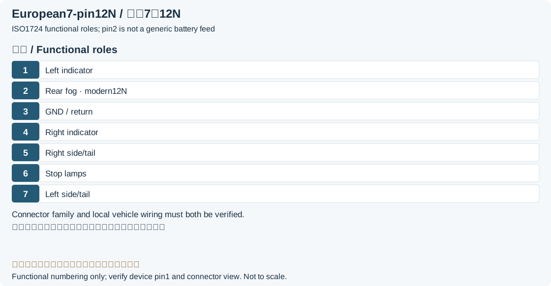
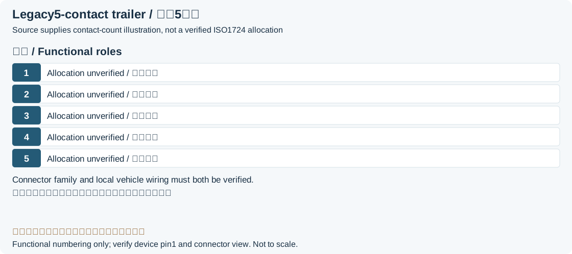
5 and 7-pin connector Type 12N (ISO 1724)
| Pin | Color | Function | Cable size |
|---|---|---|---|
| 1 | Yellow | Left Indicator | 1.5 mm² |
| 2 | Blue | Rear fog (ISO1724 12N)Legacy record: “+12V from battery or Rear fog light”. The source mixes battery power with rear fog. The cited 12N allocation assigns rear fog to 2, not a generic permanent supply. | 1.5 mm² |
| 3 | White | Earth (chassis) | 2.5 mm² |
| 4 | Green | Right Indicator | 1.5 mm² |
| 5 | Brown | Right Side lights | 1.5 mm² |
| 6 | Red | Brake lights | 1.5 mm² |
| 7 | Black | Left Side lights | 1.5 mm² |
7-pin connector Type 12S (ISO 3732)
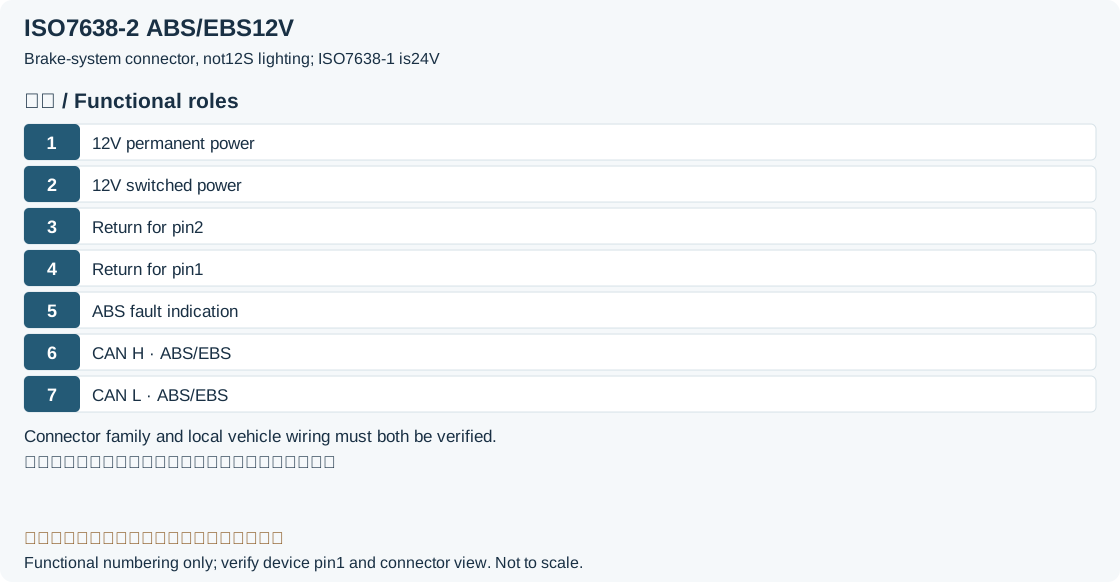
| Pin | Color | Function | Cable size |
|---|---|---|---|
| 1 | Yellow | Reversing lamps | 1.5 mm² |
| 2 | Blue | Spare | 2.5 mm² |
| 3 | White | Return for supply contact 4 (12S)Legacy record: “Common ground except for pin 6”. The manufacturer 12S note narrows this return to 4. Reverse contact 1 normally returns through contact 3 of the separate 12N connector, so “all except 6” is too broad. | 2.5 mm² |
| 4 | Green | +12V permanent | 2.5 mm² |
| 5 | Brown | Spare | 1.5 mm² |
| 6 | Red | +12V via ignition lock | 2.5 mm² |
| 7 | Black | Ground for pin 6 | 2.5 mm² |
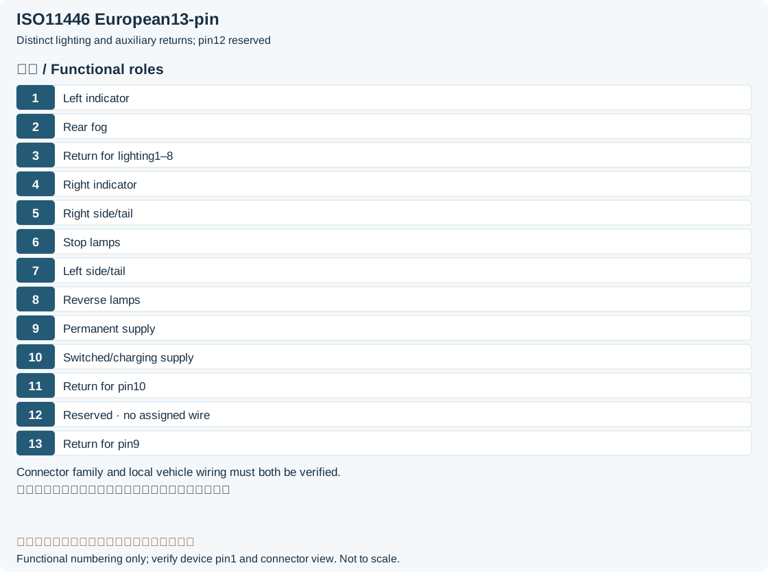
| Pin | Color | Function | Cable size |
|---|---|---|---|
| 1 | Red | +12V (permanent) | 4 mm² |
| 2 | Black | +12V (ignition key) | 1.5 mm² |
| 3 | Yellow | Earth (for pin 2) | 1.5 mm² |
| 4 | Brown | Earth (for pin 1) | 4 mm² |
| 5 | White | ABS Fault indication | 1.5 mm² |
| 6 | Green-White | CAN H, For EBS and ABS | 1.5 mm² |
| 7 | White-Brown | CAN L, For EBS and ABS | 1.5 mm² |
| Pin | Color | Function | Cable size |
|---|---|---|---|
| 1 | Yellow | Left Indicator | 1.5 mm² |
| 2 | Blue | Rear fog light | 1.5 mm² |
| 3 | White | Earth (pin 1-8) | 2.5 mm² |
| 4 | Green | Right Indicator | 1.5 mm² |
| 5 | Brown | Right Side lights | 1.5 mm² |
| 6 | Red | Brake lights | 1.5 mm² |
| 7 | Black | Left Side lights | 1.5 mm² |
| 8 | Pink | Reversing Light | 1.5 mm² |
| 9 | Orange | +12V (permanent) | 2.5 mm² |
| 10 | Grey or White-Orange | +12V (ignition key) | 2.5 mm² |
| 11 | White-Black or Green | Earth (pin 10) | 2.5 mm² |
| 12 | No assigned core (cited current manufacturer table)Legacy record: “Light Grey or Purple”. The historical light-gray/purple entry belongs to an old presence function. The current ERICH JAEGER table assigns no core to 12; those old colors are not a universal wiring instruction. | Reserved for future allocation (ISO11446 reference)Legacy record: “Trailer presence”. The source “Trailer presence” is not the cited current allocation. Legacy equipment requires its own documentation, not a generic detection short. | — (unassigned)Legacy record: “1.5 mm²”. The cited current table assigns no core/cross-section to 12. The original 1.5mm² remains in this correction for traceability, not as a requirement. |
| 13 | White-Red | Earth (pin 9) | 2.5 mm² |
US trailer connectors
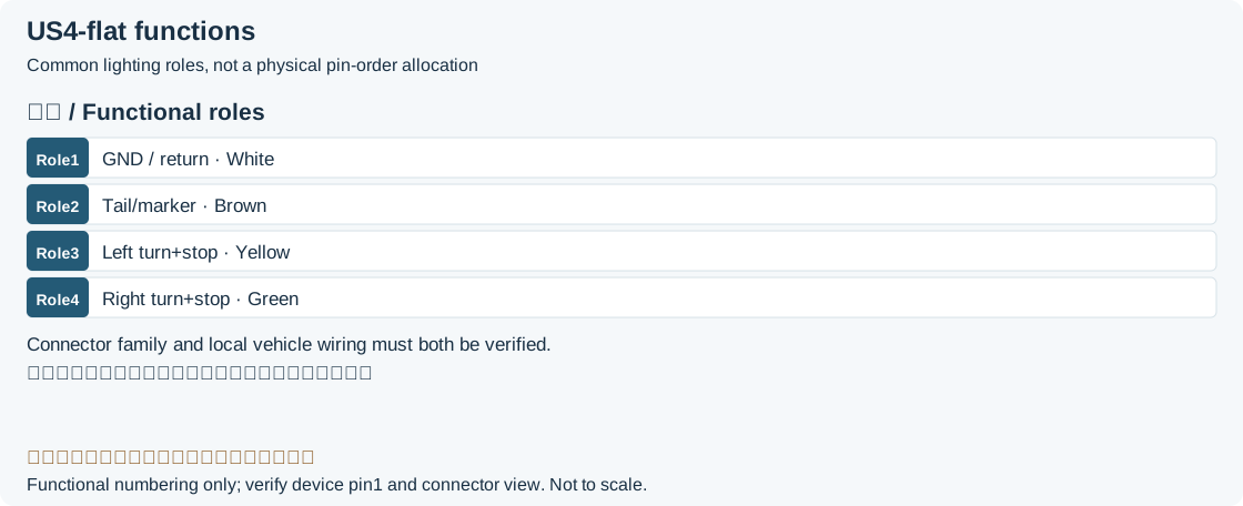
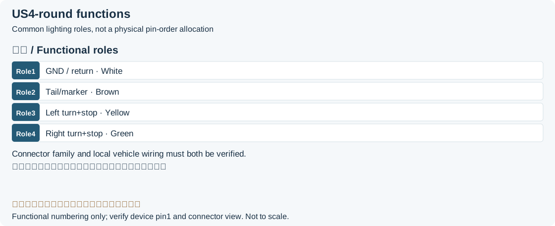
| Pin | Color | Function | Cable size |
|---|---|---|---|
| 1 | White | Earth (chassis) | 1.5 mm² |
| 2 | Brown | Tail lamps, clearance lamps/outline marker lamps and registration plate lamp | 1 mm² |
| 3 | Yellow | Left Indicator, Stop lamps | 1 mm² |
| 4 | Green | Right Indicator, Stop lamps | 1 mm² |
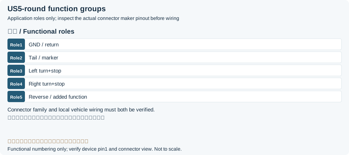
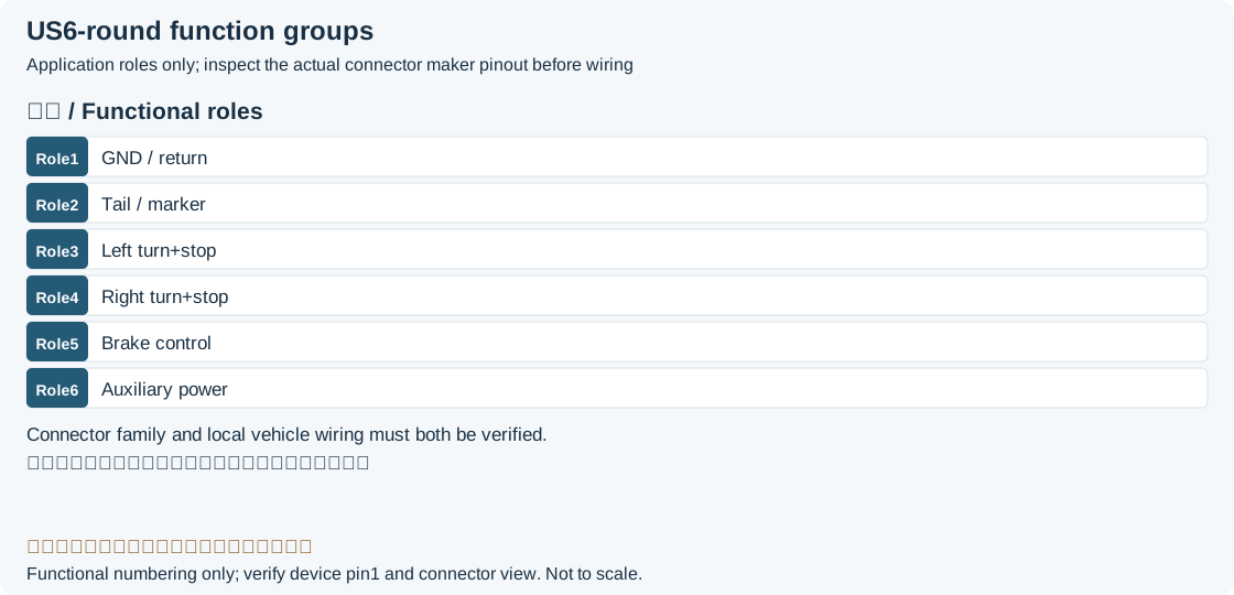
| Historical US five-pin round illustration | Historical US six-pin round illustration | Historical US seven-way blade illustration |
|---|---|---|
 |  | 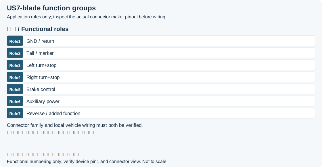 |
| Pin | Color | Function | Cable size |
|---|---|---|---|
| 1 | White | Earth (chassis) | 4 mm² |
| 2 | Yellow | Left Indicator, Stop lamps | 1.5 mm² |
| 3 | Green | Right Indicator, Stop lamps | 1.5 mm² |
| 4 | Blue | Electric brake control | 4 mm² |
| 5 | Brown | Tail lamps, clearance lamps/outline marker lamps and registration plate lamp | 1.5 mm² |
| 6 | Purple | Reversing lamps, control current to block surge brakes when reversing | 1.5 mm² |
| 7 | Black | 12V auxiliary supply; switching/protection per systemLegacy record: “+12V via ignition lock”. A US auxiliary supply is not universally ignition-switched; the historical example must not be generalized to all seven-way blade wiring. | 4 mm² |
AUS trailer connector
| Pin | Color | Function | Cable size |
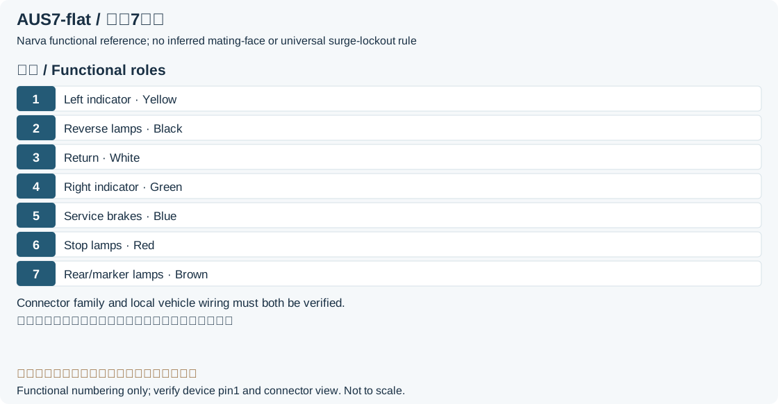
|---|---|---|---|
| 1 | Yellow | Left Indicator | 1.5 mm² |
| 2 | Black | Reversing signal; brake lockout only when documented for that systemLegacy record: “Reversing lamps, control current to block surge brakes when reversing.”. The cited Narva Australian flat-connector table assigns reverse to 2; surge-brake lockout is not a universal function on Australian trailers. | 1.5 mm² |
| 3 | White | Earth (chassis) | 2.5 mm² |
| 4 | Green | Right Indicator | 1.5 mm² |
| 5 | Blue | Electric brake control | 1.5 mm² |
| 6 | Red | Stop lamps | 1.5 mm² |
| 7 | Brown | Tail lamps, clearance lamps/outline marker lamps and registration plate lamp | 1.5 mm² |
Legacy source notes and applicability
These notes retain the legacy record. For corrected facts and applicability, use this page’s quick answer, scope and visible table corrections.
5-pin connector
5 and 7-pin connector Type 12N (ISO 1724)
7-pin connector Type 12S (ISO 3732)
7-pin connector for ABS/EBS (ISO 7638-2)
13-pin trailer connector (ISO 11446)
Pin 10, 11, 12 are not connected in 10 pole cable.
US trailer connectors
4-pin flat
4-pin round
5-pin round
6-pin round
7-pin blade
AUS trailer connector
7-pin flat AUS connector
Frequently asked questions
Does a seven-to-thirteen-contact adapter add reversing and power circuits?
It cannot create circuits absent from its input. A passive adapter only routes available signals. Reversing, refrigerator or battery-charging support depends on the vehicle harness, control module, ratings and adapter wiring.
Can the three returns in the European 13-contact system be joined?
The cited ERICH JAEGER technical note prohibits conductive joining of the three returns on the trailer: 3 serves lighting 1–8, 11 serves 10, and 13 serves 9. Shared ground terminology does not eliminate circuit grouping.
Do matching colors and contact count establish cross-region compatibility?
No. Even US SAE and Traditional configurations differ in color assignment. Australian flat, European round and ABS/EBS systems differ further. Verify voltage, keying, contact function, combined signals and control electronics.
Should contact 12 be shorted to ground for trailer detection?
The current manufacturer ISO11446 allocation used here reserves 12 and does not prescribe that short. Legacy or specialized detection circuits can differ and require their own documentation. The historical label “Trailer presence” is not a universal instruction.
Related tools and references
Sources and verification
- ERICH JAEGER: ISO11446 13-contact 12V allocation and reserved contact 12
- ERICH JAEGER technical note: 12N, 12S, 13-contact and return grouping
- ERICH JAEGER: ISO7638-1 24V versus ISO7638-2 12V
- ERICH JAEGER: 12V/24V conversion equipment and connector systems
- CURT: US 4/6/7-wire and seven-way blade SAE/Traditional differences
- Narva 82048BL manufacturer release: Australian seven-pin flat functions/colors
Legacy baseline: the Electrodoc Pro 5.2 data package. Raw records are retained and checked factual corrections are shown explicitly.