PCB TOOLS / Electronics reference
OBD-II 16-Pin Connector and DE9 Adapter Pinout
Look up OBD2 contact functions for CAN, K-line, power and grounds, and distinguish the vehicle diagnostic connector from specific DE9 and DE15 adapter cables.
Quick answer
On the 16-contact OBD-II connector, 4 is chassis ground, 5 signal ground and 16 vehicle battery positive. CAN diagnostics normally use 6 (CAN-H) and 14 (CAN-L). The DE9 example matches SparkFun CAB-10087: OBD6→DE9-3 and OBD14→DE9-5. It must not be plugged into a PC RS-232 port.
Scope
This is a contact-number/function reference, not a mechanical front-view drawing or a complete vehicle service manual. Implemented signals depend on protocol, vehicle generation and manufacturer; contacts unspecified in the traditional generic table are not necessarily unused. Type A and Type B can involve 12V and 24V systems respectively. Match equipment voltage, protocol and actual wiring.
Reading example
For a cable confirmed to use this DE9 mapping, OBD contact 6 (CAN-H) reaches DE9 contact 3, OBD14 (CAN-L) reaches DE9-5, and OBD16 (battery positive) reaches DE9-9. This lookup describes that cable only; it does not make contact 9 a battery input on other DE9 equipment.
Checked reference tables
| Item | Meaning | Not established by this alone |
|---|---|---|
| OBD-II contacts 4/5/16 | Chassis ground / signal ground / battery positive | Equipment input-voltage or fuse rating |
| CAN contacts 6/14 | H/L contacts for the applicable CAN diagnostic link | Protocol support on every vehicle |
| Non-generic contacts in the traditional table | 1, 3, 8, 9, 11, 12, 13 | NC, universal tachometer output or arbitrary power supply |
| DE9/DE15 shell | Identifies connector form only | RS-232, VGA or another diagnostic interface compatibility |
Legacy tables with visible corrections
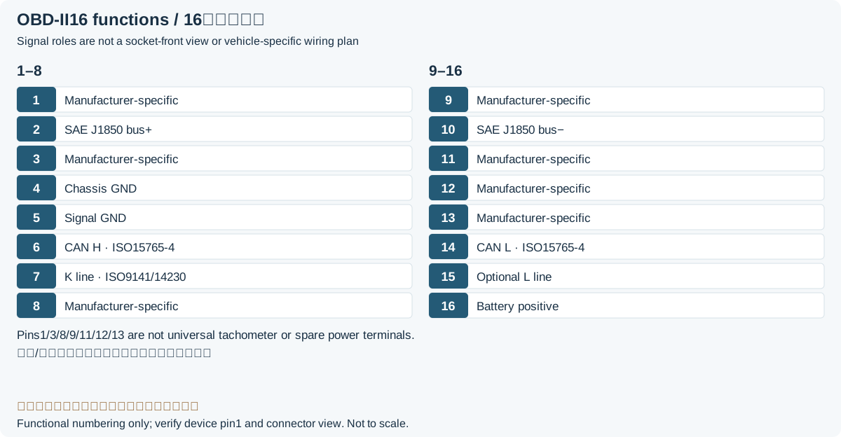
| Pin | Signal | Description |
|---|---|---|
| 1 | - | |
| 2 | J1850 Bus+ | Bus positive Line of SAE-J1850 |
| 3 | - | |
| 4 | Chassis Ground | |
| 5 | Signal Ground | |
| 6 | CAN High (J-2284) | CAN high (ISO15765-4; SAE J2284)Legacy record: “CAN high (ISO 15765-4 and J2234)”. J2234 is a source typo; the manufacturer contact reference and source signal column identify J2284. |
| 7 | ISO 9141-2 K Line | K line of ISO 9141-2 and ISO 14230-4 |
| 8 | - | |
| 9 | - | Manufacturer/model-specific; not a generic tachometer outputLegacy record: “Tachometer signal on some cars like Toyota”. The historical Toyota example does not establish a function across models, years or configurations. |
| 10 | J1850 Bus- | Bus negative Line of J1850 |
| 11 | - | |
| 12 | - | |
| 13 | - | |
| 14 | CAN Low (J-2284) | CAN low (ISO15765-4; SAE J2284)Legacy record: “CAN low (ISO 15765-4 AND J2234)”. Corrects the mistyped standard number without changing contact 14 as CAN-L. |
| 15 | ISO 9141-2 L Line | L line of ISO 9141-2 and ISO 14230-4 |
| 16 | Battery Power |
OBD-II to DE9 Cable
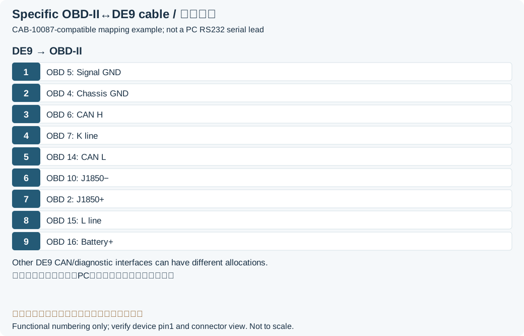
| DE-9 | OBD-II | Signal |
|---|---|---|
| 1 | 5 | Signal Ground |
| 2 | 4 | Chassis Ground |
| 3 | 6 | CAN High (J-2284) |
| 4 | 7 | ISO 9141-2 K Line |
| 5 | 14 | CAN Low (J-2284) |
| 6 | 10 | J1850 Bus- |
| 7 | 2 | J1850 Bus+ |
| 8 | 15 | ISO 9141-2 L Line |
| 9 | 16 | Battery Power |
OBD-II to DE15 Cable
| DE-15S | OBD-II | Signal |
|---|---|---|
| 1 | 1 | |
| 2 | 2 | J1850 Bus+ |
| 3 | 3 | |
| 4 | 4 | Chassis Ground |
| 5 | 5 | Signal ground |
| 6 | 6 | |
| 7 | 7 | ISO 9141-2 K Line |
| 8 | 8 | |
| 9 | 9 | |
| 10 | 10 | J1850 Bus- |
| 11 | 11 | |
| 12 | 12 | |
| 13 | 16 | Battery Power |
| 14 | 14 | |
| 15 | 15 | ISO 9141-2 L Line |
Legacy source notes and applicability
These notes retain the legacy record. For corrected facts and applicability, use this page’s quick answer, scope and visible table corrections.
The location of the OBD II socket is generally on the driver's side of the car under the steering wheel.
The unspecified pins are left for car manufactures use. They can differ depending on the car manufacture and model.
OBD-II to DE9 Cable
Note: This cable is not meant to be plugged directly into a computer's serial port. It is meant to plug into some sort of hardware interface.
OBD-II to DE15 Cable
Outer shield is tied to pin 4
OBD II Standard Fault Codes
P00xx Fuel and Air Metering
P01xx Fuel and Air Metering
P02xx Fuel and Air Metering
P03xx Ignition System and Misfire Detection
P04xx Auxilliary Emission Controls. EGR, EVAP etc.
P05xx Vehicle Speed, Idle Control, and Auxiliary Inputs
P06xx Computer and Auxiliary Outputs
P07xx Transmission
Frequently asked questions
Why is a DE9 connector not automatically a serial port?
The shell does not determine the electrical interface. This cable brings battery, grounds and CAN/K/J1850 signals to DE9. RS-232 uses different contact functions, levels and transceivers. Use the specified compatible diagnostic interface.
Are OBD contacts 6 and 14 active on every vehicle?
No. They are the CAN diagnostic contacts in this reference. Older vehicles can use other protocols, and other networks or DoIP have additional requirements. Check the vehicle documentation and diagnostic interface specification.
Can contact 9 be used as a generic tachometer output?
No. It is not a universal contact in the traditional generic table. A historical example does not establish the function on all Toyota or other vehicles. Use documentation for the exact model, year and configuration.
Related tools and references
Sources and verification
- DashLogic: J1962 contacts and manufacturer-discretionary positions
- SparkFun CAB-10087: DE9 mapping and serial-port restriction
- CSS Electronics: connector, protocol and Type A/B voltage context
- SECONS OBDTester: diagnostic connector and separate DoIP examples
Legacy baseline: the Electrodoc Pro 5.2 data package. Raw records are retained and checked factual corrections are shown explicitly.