PCB TOOLS / Electronics reference
Car Audio ISO Connector Pinout: Power, Speakers and Mini-ISO
Look up power, four speaker pairs and historical mini-ISO functions by the car-radio connector’s A/B/C regions, with distinctions between battery, ACC and paired speaker outputs.
Quick answer
A common arrangement uses A4 for permanent battery power, A7 for ignition/ACC and A8 for ground, but some vehicles interchange A4 and A7. B1/2, B3/4, B5/6 and B7/8 are the rear-right, front-right, front-left and rear-left speaker pairs respectively. A speaker “−” in block B is not chassis ground.
Scope
The A/B tables explain common 12V car-radio connections. C1/C2/C3 are historical equipment examples and are not implemented identically on every head unit or vehicle. The drawing groups numbers and functions without specifying a mating or solder view. Standard scope, supported device functions, harness colors and output-current ratings are separate matters; use the exact model’s manual.
Reading example
For the front-right speaker, B3 is positive and B4 negative: they form one channel pair, so B4 must not be joined to A8. The Kenwood DMX9724XDS manual defaults to A4 battery and A7 ACC and explicitly shows vehicles where they are reversed. A generic color alone cannot settle the connection.
Checked reference tables
| Contact type | Example here | Meaning |
|---|---|---|
| Power/chassis ground | A8 | Designated supply reference and return |
| Paired speaker output | B3 (+), B4 (−) | Two front-right channel outputs; negative is not a common ground |
| Line-output reference ground | C1 / pin 3 | Contact 3 within historical region C1 is the line-signal reference, not a speaker negative output |
Legacy tables with visible corrections
ISO 10487 car connector
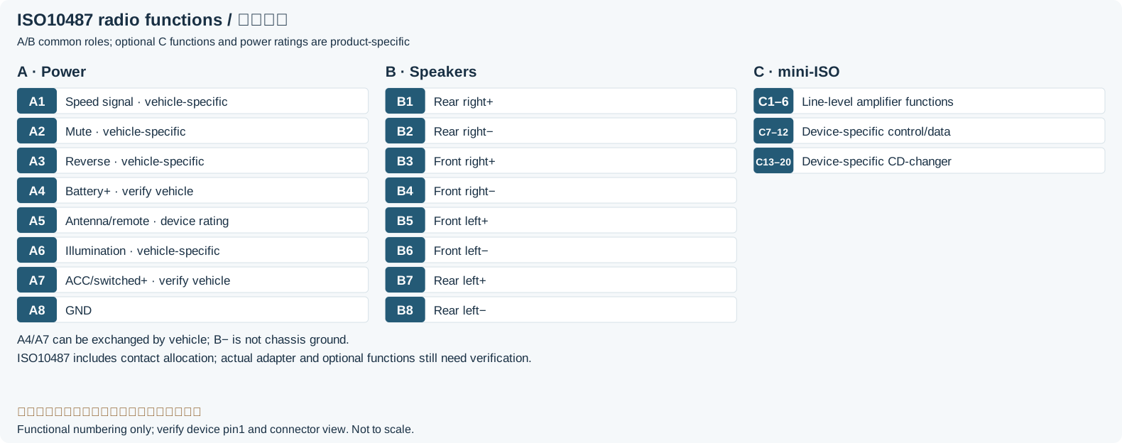
ISO-A connector (Power)
| Pin | Signal | |
|---|---|---|
| 1 | Speed signal (speed-dependent volume control) | |
| 2 | Phone Mute | |
| 3 | Reversing light switch (used for satellite navigation) | |
| 4 | +12V from Battery | |
| 5 | Antenna/power-control output; voltage and current limit per head-unit manualLegacy record: “Power for electronic Antenna (+12V output 150-300mA)”. The source +12V, 150–300mA is a historical example, not a rating for all ISO head units; the cited Kenwood model specifies a different 350mA combined control output. | |
| 6 | Illumination (+12 V input when the lights are on) | |
| 7 | +12V Power (Switched via Ignition key) | |
| 8 | Ground | |
ISO-B connector (Loudspeaker)
| Pin | Signal | |
|---|---|---|
| 1 | Right Rear + | |
| 2 | Right Rear - | |
| 3 | Right Front + | |
| 4 | Right Front - | |
| 5 | Left Front + | |
| 6 | Left Front - | |
| 7 | Left Rear + | |
| 8 | Left Rear - | |
ISO-C connector [mini-ISO]
| Pin | Signal | |
|---|---|---|
| 1 | Line out Rear Left | |
| 2 | Line out Rear Right | |
| 3 | Line out common Ground | |
| 4 | Line out Front Left | |
| 5 | Line out Front Right | |
| 6 | Switched supply; device-specific, source example +12V/150mALegacy record: “+12V switched (max 150mA)”. Retains the source figures for traceability without assigning that capability to other equipment. | |
| 7 | Receive Data | |
| 8 | Transmit Data | |
| 9 | Chassis Ground | |
| 10 | Switched supply; device-specific, source example +12V/150mALegacy record: “+12V switched (max 150mA)”. Mini-ISO supply and current limits require the specific head-unit documentation; this is not a universal rating. | |
| 11 | Remote control In | |
| 12 | Remote control Ground | |
| 13 | CDC Data In | |
| 14 | CDC Data Out | |
| 15 | CDC +12V permanent | |
| 16 | Changer switched supply; device-specific, source example +12V/300mALegacy record: “CDC +12V switched (max 300mA)”. The source 300mA is a historical equipment example, not a guarantee for any changer or accessory module. | |
| 17 | CDC Data Ground) | |
| 18 | CDC Audio Ground | |
| 19 | CDC Audio Left | |
| 20 | CDC Audio Right | |
Legacy source notes and applicability
These notes retain the legacy record. For corrected facts and applicability, use this page’s quick answer, scope and visible table corrections.
ISO 10487 connector
ISO-A connector (Power)
On some cars the +12V Ignition and Battery positions are reversed
ISO-B connector (Loudspeaker)
ISO-C connector [mini-ISO]
C1 (external amplifier)
C2 (remote control)
C3 (CD changer)
ISO 10487 only defines the physical attributes of the connectors, not the pin/signal designations.
The connector wiring depends on the manufacturer.
Frequently asked questions
Does lost memory with ignition off justify swapping A4/A7 immediately?
The symptom alone is insufficient. Battery/ACC arrangements do vary, but adapter wiring, fuses, network control or device settings can also matter. Confirm both contacts from the exact vehicle and head-unit documentation.
Why is a block-B negative terminal not ground?
The signs identify the two terminals of a speaker channel. In BTL operation both are driven by the amplifier, while chassis ground belongs to designated return circuits such as A8. Grounding a negative speaker output changes or shorts that output.
Can any CD changer or AUX module be connected to C1/C2/C3?
No. Verify the head-unit model, contacts, power control, levels, communication protocol and enabled functions. Shared labels such as “Data” or “Ground” do not prove compatibility.
Related tools and references
Sources and verification
- ISO10487-1 official abstract: includes contact allocation
- JVCKENWOOD DMX9724XDS: A/B contacts and A4/A7 variation
- Texas Instruments SLAU375C §2.3: do not ground BTL speaker outputs
Legacy baseline: the Electrodoc Pro 5.2 data package. Raw records are retained and checked factual corrections are shown explicitly.