PCB TOOLS / PINOUT & INTERFACE REFERENCE
Raspberry Pi 26 / 40-Pin GPIO and Legacy Revisions
Look up physical pins, BCM GPIO, I²C/SPI/UART functions and early Rev1/Rev2 differences. The historical source covers A/B through Pi 4; Pi 4 extra alternate functions are not a Pi 5 mapping.
Quick answer
Physical pins 3 and 5 on Rev2 and the later listed boards are normally GPIO2/SDA1 and GPIO3/SCL1; early Rev1 uses GPIO0/SDA0 and GPIO1/SCL0. Pins 27/28 of a 40-pin header are ID_SD/ID_SC for HAT identification. GPIO signals are 3.3 V and are not 5 V tolerant.
Scope
Retains the source early 26-pin P1, 40-pin and Pi4 extra columns. Pi4 extra describes BCM2711 alternate functions, not Pi 5/RP1. Multiple functions on one pin need software selection and cannot all be arbitrarily enabled together. The specifications are a historical snapshot, not a current product/RAM catalogue or supply recommendation.
Reading example
For a 3.3 V I²C sensor on a confirmed Rev2 or later listed board, connect SDA to physical pin 3 (BCM GPIO2), SCL to physical pin 5 (BCM GPIO3) and share ground. GPIO2 in software does not mean physical pin 2, which is a 5 V supply pin.
Interfaces, pinouts and technical reference
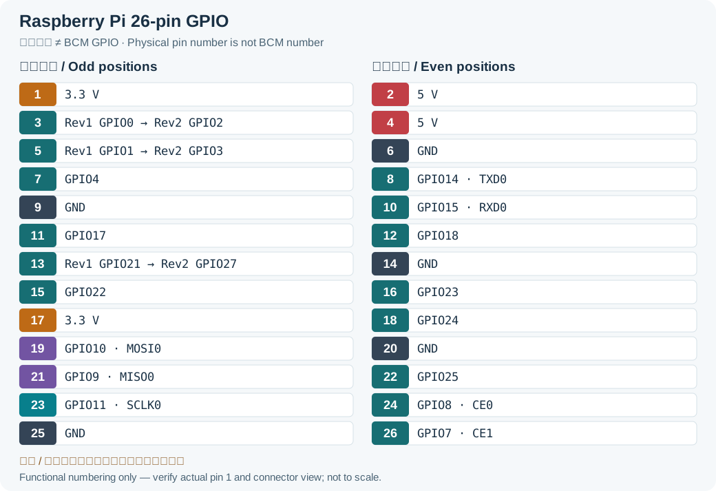
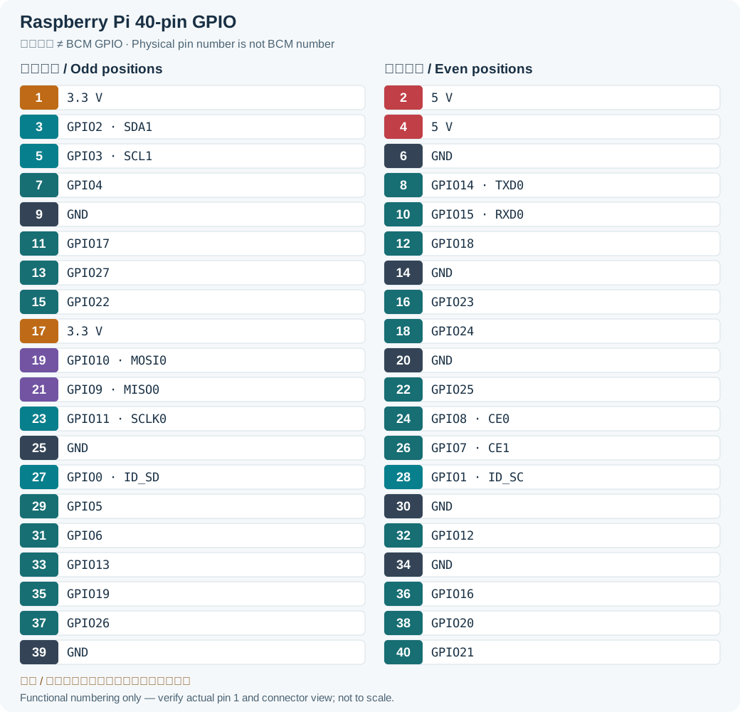
| Row1 Signal | Pin | Pin | Row2 Signal | |||||
|---|---|---|---|---|---|---|---|---|
| Pi Rev1 | Pi Rev2 Pi+, Pi0, Pi2, Pi3, Pi4 | Pi4 extra | Pi Rev1 | Pi Rev2 Pi+, Pi0, Pi2, Pi3, Pi4 | Pi4 extra | |||
| 3.3 V | 1 | 2 | 5 V | |||||
| GPIO 0 | GPIO 2 | SPI3 MOSI | 3 | 4 | 5 V | |||
| I²C0 SDA | I²C1 SDA | I²C3 SDA | ||||||
| GPIO 1 | GPIO 3 | SPI3 SCLK | 5 | 6 | Ground | |||
| I²C0 SCL | I²C1 SCL | I²C3 SCL | ||||||
| GPIO 4 | SPI4 CE0 | 7 | 8 | GPIO 14 | SPI5 MOSI | |||
| UART3 TX | ||||||||
| I²C3 SDA | UART0 TX | UART1 TX | ||||||
| Ground | 9 | 10 | GPIO 15 | SPI5 SCLK | ||||
| UART0 RX | UART1 RX | |||||||
| GPIO 17 | 11 | 12 | GPIO 18 | |||||
| SPI1 CE1 | SPI1 CE0 | SPI6 CE0 | ||||||
| GPIO 21 | GPIO 27 | SPI6 CE1 | 13 | 14 | Ground | |||
| GPIO 22 | I²C6 SDA | 15 | 16 | GPIO 23 | I²C6 SCL | |||
| 3.3 V | 17 | 18 | GPIO 24 | SPI3 CE1 | ||||
| GPIO 10 | 19 | 20 | Ground | |||||
| SPI0 MOSI | I²C5 SDA | |||||||
| GPIO 9 | UART4 RX | 21 | 22 | GPIO 25 | SPI4 CE1 | |||
| SPI0 MISO | I²C4 SCL | |||||||
| GPIO 11 | 23 | 24 | GPIO 8 | UART4 TX | ||||
| SPI0 SCLK | I²C5 SCL | SPI0 CE0 | I²C4 SDA | |||||
| Ground | 25 | 26 | GPIO 7 | I²C4 SCL | ||||
| SPI0 CE1 | SPI4 SCLK | |||||||
| ID_SDLegacy record: “IS_SD”. Source IS_SD is a typo; the official HAT identification signal on physical pin 27 is ID_SD. | SPI3 CE0 | 27 | 28 | ID_SCLegacy record: “IS_SC”. Source IS_SC is a typo; the official HAT identification signal on physical pin 28 is ID_SC. | SPI3 MISO | |||
| GPIO 0 | UART2 TX | GPIO 1 | UART2 RX | |||||
| I²C0 SDA | I²C6 SDA | I²C0 SCL | I²C6 SCL | |||||
| GPIO 5 | SPI4 MISO | 29 | 30 | Ground | ||||
| UART3 RX | ||||||||
| I²C3 SCL | ||||||||
| GPIO 6 | SPI4 MOSI | 31 | 32 | GPIO 12 | SPI5 CE0 | |||
| I²C4 SDA | I²C5 SDA | |||||||
| UART5 TX | ||||||||
| GPIO 13 | SPI5 MISO | 33 | 34 | Ground | ||||
| I²C5 SCL | ||||||||
| UART5 RX | ||||||||
| GPIO 19 | 35 | 36 | GPIO 16 | SPI1 CE2 | ||||
| SPI1 MISO | SPI6 MISO | |||||||
| GPIO 26 | SPI5 CE1 | 37 | 38 | GPIO 20 | SPI6 MOSI | |||
| SPI1 MOSI | ||||||||
| Ground | 39 | 40 | GPIO 21 | SPI6 SCLK | ||||
| SPI1 SCLK | ||||||||
Raspberry Pi Technical Specifications
| Pi A | Pi A+ | Pi B | Pi B+ | Pi2 B | Pi3 B | Pi3 B+ | Pi4 B | Pi 0 | Pi 0 W | |
|---|---|---|---|---|---|---|---|---|---|---|
| SoC | Broadcom BCM2835 | Broadcom BCM2836 | Broadcom BCM2837 | Broadcom BCM2837B0 | Broadcom BCM2711 | Broadcom BCM2835 | ||||
| CPU | 700MHz ARM1176JZF-S | 900MHz 4x ARM Cortex-A7 | 1.2GHz 4x ARM Cortex-A53 | 1.4GHz 4x ARM Cortex-A53 | 1.5GHz 4x ARM Cortex-A72 | 1GHz ARM1176JZF-S | ||||
| GPU | Broadcom VideoCore IV @ 250 MHz, OpenGL ES 2.0, 1080p30 H.264 high-profile decoder and encoder (BCM2837: 1080p60) | Broadcom VideoCore VI @ 500 MHz, OpenGL ES 3.x, HEVC 4K 60 fps | Broadcom VideoCore IV @ 250 MHz, OpenGL ES 2.0, 1080p30 H.264 high-profile decoder and encoder | |||||||
| RAM | 256 MB | 256/512 MB | 1 GB | 1/2/4 GB | 512 MB | |||||
| USB2 | 1 | 2 | 4 | 2 | 1 (micro) | |||||
| USB3 | 0 | 2 | 0 | |||||||
| Video output | HDMI (rev 1.3) | 2x micro-HDMI (rev 2.0) | Mini-HDMI | |||||||
| composite (RCA jack) | composite (3.5mm jack) | composite (RCA jack) | composite (3.5mm jack) | composite via GPIO | ||||||
| Audio output | HDMI, 3.5mm jack | Mini-HDMI, PWM on GPIO | ||||||||
| Storage | SD/MMC/SDIO | microSD | SD/MMC/SDIO | microSD | ||||||
| Network | - | 10/100 Ethernet | 10/100 Ethernet, 802.11n WiFi, Bluetooth 4.1 | 10/100/1000 Ethernet, 802.11ac WiFi, Bluetooth 4.2 | 10/100/1000 Ethernet, 802.11ac WiFi, Bluetooth 5.0 | - | 802.11n WiFi, Bluetooth 4.1 | |||
| Peripherals | 26 pin GPIO header | 40 pin GPIO header | 26 pin GPIO header | 40 pin GPIO header | ||||||
| Power ratings | 300mA (1.5W) | 200mA (1W) | 700mA (3.5W) | 200mA (1W) idle 350mA (1.75W) max | 220mA (1.1W) idle 820mA (4.1 W) max | 300mA (1.5W) idle 1.3A (6.5 W) max | 450mA (2.25W) idle 1.1A (5.5 W) max | 3 A (15W) | 100mA (0.5W) idle 350mA (1.75W) max | |
| Size (mm) | 85.6 x 56.5 | 65 x 56.5 | 85.60 x 56.5 | 65 x 30 | ||||||
Legacy source notes and applicability
These notes retain the legacy record. For corrected facts and applicability, use this page’s quick answer, scope and visible table corrections.
Raspberry Pi A+/B+ and Raspberry Pi0/Pi2/Pi3/Pi4 header (GPIO)
Notes:
Voltage levels are 3.3V (NOT 5V tolerant). There is no over-voltage protection on the board.
The maximum permitted current draw from the 3.3 V pin is 50 mA.
The GPIO pins are unbuffered and unprotected.
Pin 3-5 (SDA/SCL) have 1.8 kΩ pulls up resistors on the board.
Pin 27-40 are only available on Raspberry Pi A+/B+, Raspberry Pi0, Pi2, Pi3 and Pi4.
Pin IS_SD-IS_SC are reserved for ID EEPROM.
Raspberry Pi Technical Specifications
Frequently asked questions
How do physical and BCM numbering differ?
Physical numbers describe header positions 1–26 or 1–40; BCM numbers identify SoC GPIO signals. Early revisions changed the GPIO at physical pin 3, so check both revision and numbering scheme.
Can Pi4 extra be used directly on Pi 5?
No. Similar header positions for common power/GPIO signals do not imply identical SoC alternate functions. Pi 5 has a different I/O architecture; use its official Pi 5/RP1 documentation and system configuration.
Why does one diagram show only 26 pins?
It represents the early A/B P1 header. A+/B+ and the later listed boards use 40 pins. Early Rev1 also differs at physical pins 3, 5 and 13.
Related tools and references
Sources and verification
- Raspberry Pi: GPIO, reserved pins and BCM2711 alternate functions
- Raspberry Pi HAT design guide: ID_SD / ID_SC
- Raspberry Pi BCM2711 peripherals and alternate functions
Legacy baseline: the Electrodoc Pro 5.2 data package. Raw records are retained and checked factual corrections are shown explicitly.