PCB TOOLS / Electronics reference
MIDI pinout: 5-pin DIN and 3.5mm TRS Type A/B
Look up the MIDI DIN 5 current loop, shield and IN/OUT direction, then compare TRS MIDI Type A/B. Visible corrections identify reversed source/sink names on pins 4/5 and qualify the original blanket ground label on pin 2.
Quick answer
DIN MIDI uses pins 4/5 for its current loop; standard equipment leaves1/3 unconnected. From the transmitter, pin 4 is the source side and pin 5 the data-controlled return/sink side. Pin2 carries cable shielding; MIDI IN has no DC connection to receiver ground. TRS Type A maps Tip→5, Ring→4, Sleeve→2; Type B swaps Tip/Ring.
Scope
Scope: MIDI 1.0 DIN 5 electrical connections and TRS adapter identification; excludes USB-MIDI, MIDI 2.0 network transports, DIN Sync and proprietary spare-pin power. The diagram is functional numbering, not a verified male/female mating or solder-side view.
Reading example
For keyboard MIDI OUT to sound-module MIDI IN, check both port labels. A module requiring TRS Type A needs DIN 5 pin 5→Tip, pin 4→Ring, pin 2→Sleeve; Type B reverses the signal pair. The adapter changes connections and does not convert analog audio into MIDI.
Checked reference tables
| Contact | Type A | Type B(legacy implementation) |
|---|---|---|
| Tip | DIN5:5 | DIN5:4 |
| Ring | DIN5:4 | DIN5:5 |
| Sleeve | DIN5:2 | DIN5:2 |
A/B look identical; verify the exact device requirement.
Legacy tables with visible corrections
Musical Instrument Digital Interface
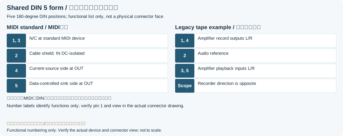
| Pin | Name | Description |
|---|---|---|
| 1 | N/C | Not connected |
| 2 | Shield(grounded at OUT/THRU; DC-isolated at IN)Legacy record: “GND”. The original GND label did not distinguish transmitter and receiver. | Cable shield; not directly grounded at MIDI INLegacy record: “Ground”. CA-033 requires no DC ground path at IN; small-capacitor RF coupling is optional. |
| 3 | N/C | Not connected |
| 4 | CSRCLegacy record: “CSINK”. From MIDI OUT, pin 4 is the current-source side; the source/sink names were reversed. | Current-source side(transmitter naming)Legacy record: “Current Sink”. Pin4 connects through the transmitter current-limiting network; it is not a general supply output. |
| 5 | CSINKLegacy record: “CSRC”. From MIDI OUT, pin 5 is the data-controlled sink/return side. | Data-controlled current-sink/return sideLegacy record: “Current Source”. Together with 4, it drives the receiver optocoupler loop; the original name was reversed. |
Legacy source notes and applicability
These notes retain the legacy record. For corrected facts and applicability, use this page’s quick answer, scope and visible table corrections.
5 pin DIN female connector (at the peripheral)
Since the game port moved to sound cards, these connectors usually double as connectors for MIDI instruments; two of the redundant +5V and GND pins of the original standard were rededicated to MIDI input and output.
Frequently asked questions
Can I identify TRS A/B from the 3.5mm plug shape?
No. The shape is the same; check the device manual and adapter continuity. Type A follows the MIDI Association TRS allocation; Type B is a legacy implementation used by some equipment.
How do MIDI OUT, IN and THRU differ?
OUT transmits local data, IN receives, and traditional THRU forwards received IN data. Identical connectors do not make directions interchangeable; do not arbitrarily parallel several inputs on one output.
Can a DIN audio cable automatically serve as MIDI cable?
Verify continuity, shielding and intended use. The DIN shape does not ensure an audio cable carries the required4/5/2 connections or meets the MIDI electrical interface.
Related tools and references
Sources and verification
- MIDI Association/AMEI: CA-033 Electrical Specification Update(2014), Figures1–3
- MIDI Association: TRS adapter specification release and scope
- KORG: Type A/B incompatibility and KORG Type A requirement
- Roland/BOSS official:explicit Type A/B mapping to DIN4/5/2
Legacy baseline: the Electrodoc Pro 5.2 data package. Raw records are retained and checked factual corrections are shown explicitly.