PCB TOOLS / Electronics reference
DIN audio pinout: legacy 5-pin record/playback directions
Compare amplifier and tape-recorder directions in a legacy DIN 5 audio example: record, playback, left/right and pin 2 reference. Original two-level headers and the shared Ground cell remain; the same DIN shape does not imply MIDI or power compatibility.
Quick answer
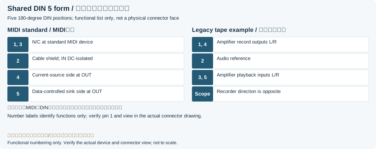
In this archived example, the amplifier sends left/right recording signals on 1/4 and receives left/right playback on 3/5. The recorder has the opposite input/output roles, and pin 2 is the shared reference. Header order is1, 4, 2, 5, 3, not sequential pin numbering; check TAPE, AUX and powered DIN sockets separately.
Scope
A reading reference for a historical5-pin 180°DIN bidirectional stereo tape interface, not a universal allocation for every DIN socket. Levels, impedances, occupied contacts and auxiliary power depend on equipment. The original diagram does not define male/female mating or solder-side positions.
Reading example
To record from the example amplifier, its pin 1 left output feeds recorder pin 1 left input and pin 4 right output feeds recorder pin 4 right input; verify the pin 2 reference. Playback uses recorder outputs3/5. A DIN-to-two-RCA lead wired only to 3/5 may play back but cannot carry this recording direction.
Legacy tables with visible corrections
| Peripheral | Pin function | ||||
|---|---|---|---|---|---|
| 1 | 4 | 2 | 5 | 3 | |
| Amplifier | Left out | Right out | Ground | Right in | Left in |
| Tape recorder | Left in | Right in | Right out | Left out | |
Legacy source notes and applicability
These notes retain the legacy record. For corrected facts and applicability, use this page’s quick answer, scope and visible table corrections.
Mono devices use only pin 1-2-3.
Frequently asked questions
Why does a pin change from input to output between rows?
The rows describe the amplifier and recorder respectively. A signal runs from one device output into the other input; read the row label as well as Left in/out.
Can I wire DIN-to-RCA by red/white colors alone?
No. Colors may identify channels but do not guarantee record/play direction or DIN pin numbers; confirm documentation and unpowered continuity.
Are DIN audio and DIN MIDI interchangeable?
The shape alone does not permit interchange. MIDI uses a digital current loop on 4/5; this audio example carries analog channels and has different pin 2 grounding requirements.
Related tools and references
Sources and verification
- Naim official preamplifier manual: model-specific inputs, record outputs and auxiliary power
- MIDI Association: different electrical use of the same DIN 5 form
Legacy baseline: the Electrodoc Pro 5.2 data package. Raw records are retained and checked factual corrections are shown explicitly.