PCB TOOLS / Electronics reference
SCART audio/video pinout
Look up SCART stereo audio, composite video, RGB, blanking and aspect signaling, with conditional S-Video/component extensions.
Quick answer
Pins1/3 are right/left audio outputs, 2/6 inputs; 19 composite output, 20 input, and 16 RGB selection.
Scope
Input/output are device-port roles; source up/down means toward/from TV.S-Video is conditional, YPbPr non-standard, and the drawing is not a verified receptacle face.
Reading example
For TV composite input, look up20 and return 17; do not mix pin 8 aspect levels with pin 16 fast blanking.
Legacy tables with visible corrections
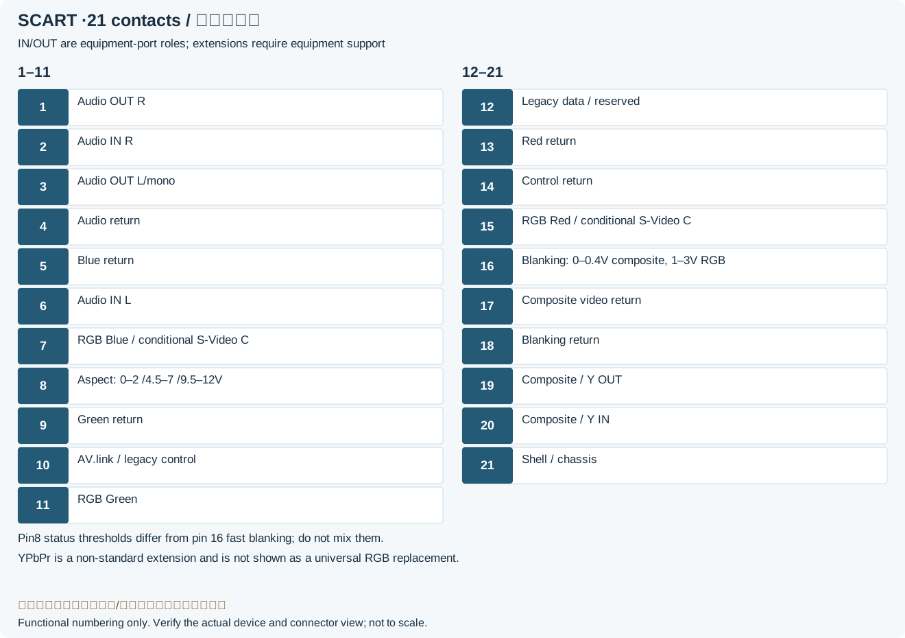
| Pin | Description |
|---|---|
| 1 | Audio output (right) |
| 2 | Audio input (right) |
| 3 | Audio output (left/mono) |
| 4 | Audio ground |
| 5 | RGB Blue ground (pin 7 ground) |
| 6 | Audio input (left/mono) |
| 7 | RGB Blue up S-Video C down ⁽¹⁾ Component Pb up ⁽²⁾ |
| 8 | Status/aspect toward TV: 0–2V inactive; 4.5–7V16: 9; 9.5–12V4: 3Legacy record: “Status & Aspect Ratio up ⁽³⁾ • 0–0.4V → off • 5–8V → 16:9 • 9.5–12V → on/4:3”. Analog Devices distinguishes pin 8 status from pin 16 fast blanking; the archive mixed their thresholds. |
| 9 | RGB Green ground (pin 11 ground) |
| 10 | Clock / Data 2 ⁽⁴⁾ Control bus (AV.link) |
| 11 | RGB Green up Component Y up ⁽²⁾ |
| 12 | Reserved / Data 1 ⁽⁴⁾ |
| 13 | RGB Red ground (pin 15 ground) |
| 14 | Data signal ground (pins 8, 10 & 12 ground) |
| 15 | RGB Red up S-Video C up Component Pr up ⁽²⁾ |
| 16 | Blanking signal up RGB-selection voltage up • 0–0.4V → composite • 1–3V → RGB |
| 17 | Composite video ground (pin 19 & 20 ground) |
| 18 | Blanking signal ground (pin 16 ground) |
| 19 | Composite video output S-Video Y output |
| 20 | Composite video input S-Video Y input |
| 21 | Shell/Chassis ⁽⁶⁾ |
| ⁽¹⁾ rarely supported. ⁽²⁾ non-standard extension. ⁽³⁾ from STB to VCR when used for unattended recording ⁽⁴⁾ protocol not standardised, e.g. D²B ⁽⁵⁾ bi-directional bus ⁽⁶⁾ This pin is part of the shell/surround of the male connector. It is often connected to the overall screen in a cheap cable. In equipment, Pin 21 should be connected separately to the chassis, but often it is merely connected to all the other ground pins. output/input denotes symmetrical links up/down denotes links to/from the TV set | |
Frequently asked questions
Does every SCART adapter provide RGB?
No.Source, cable and television must support RGB and blanking.
Can pin 21 replace every signal return?
No.Pin21 concerns shell/chassis; audio, video and controls have designated returns.
Related tools and references
Sources and verification
Legacy baseline: the Electrodoc Pro 5.2 data package. Raw records are retained and checked factual corrections are shown explicitly.