PCB TOOLS / Electronics reference
PS/2 and AT keyboard pinout
Look up Data, Clock, +5V and return for 6-pin mini-DIN PS/2 and 5-pin DIN AT keyboards, including splitter exceptions.
Quick answer
PS/2: 1 Data, 3GND, 4VCC, 5 Clock; AT: 1 Clock, 2 Data, 4GND, 5VCC.
Scope
PS/2 pins 2/6 are normally reserved and repurposed only by specific splitters; AT/XT shapes do not guarantee protocol compatibility.Diagrams do not define mating/solder views.
Reading example
For Clock, AT pin 1 corresponds to PS/2 pin 5; matching numbers are not the mapping.
Legacy tables with visible corrections
PS/2 connector
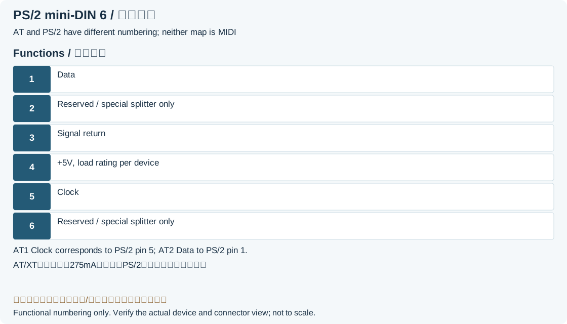
| Pin | Name | Description |
|---|---|---|
| 1 | +DATA | Data |
| 2 | N/C | Not connected (*) |
| 3 | GND | Ground |
| 4 | VCC | +5V DC; archived 275mA is device-specific, not a universal ratingLegacy record: “+5V DC @ 275 mA”. The signal allocation does not mean every PS/2 device draws275mA. |
| 5 | +CLK | Clock |
| 6 | N/C | Not connected (**) |
| Color | Description |
|---|---|
| Purple | Keyboard |
| Green | Mouse |
AT keyboard connector
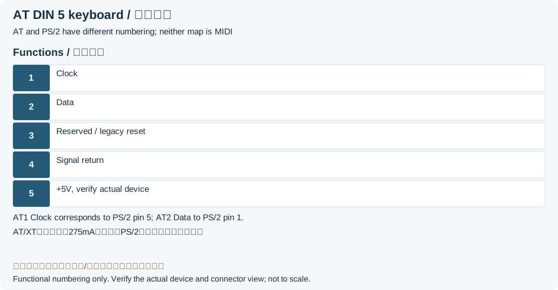
| Pin | Name | Description |
|---|---|---|
| 1 | CLK | Clock signal |
| 2 | DATA | Data |
| 3 | N/C | Not connected. Reset on older keyboards |
| 4 | GND | Ground |
| 5 | VCC | +5V DC |
Legacy source notes and applicability
These notes retain the legacy record. For corrected facts and applicability, use this page’s quick answer, scope and visible table corrections.
(*) On some computers mouse data for splitter cable.
(**) On some computers mouse clock for splitter cable.
AT keyboard connector
Frequently asked questions
Does a passive PS/2-to-USB adapter work with every keyboard?
Only with a device supporting both protocols; otherwise an active converter is required.
Do purple/green colors prove the circuitry?
They are common keyboard/mouse labels; combined or unusual ports require the manual.
Related tools and references
Sources and verification
Legacy baseline: the Electrodoc Pro 5.2 data package. Raw records are retained and checked factual corrections are shown explicitly.