PCB TOOLS / Electronics reference
PoE Pinout and Standards: Mode A/B, Four-Pair Power and Classes
Look up PoE power contacts, T568A/B colors and Type 1–4 power levels. Distinguish PSE output from PD input, detection/classification and non-standard passive power. Legacy tables remain with visible power and loop-unit corrections.
Quick answer
Mode A supplies power through contact groups 1/2 and 3/6; Mode B uses 4/5 and 7/8. Four-pair PoE uses both power loops. For Type 4 Class 8, compare the normal 90 W PSE budget and guaranteed available 71.3 W at the PD. The source’s 100 W is not guaranteed on every standards-compliant port, and these normal budgets are not absolute extended-power ceilings.
Scope
PSE means power sourcing equipment and PD means powered device. Standards-based PoE detects a compatible PD signature before applying normal operating voltage, then allocates power through physical classification and applicable data-link mechanisms. Detection, classification and Ethernet speed negotiation are distinct. Mode A/B describes contact groups, not T568A/B wiring. Gigabit and faster links use all four data pairs; “spare pairs” applies only to some 10/100 cases. Diagrams show functional numbering, not an assumed plug/jack viewing direction.
Reading example
A PD requiring 20 W input exceeds the Type 1 12.95 W level. A Type 2 allocation up to 25.5 W may suffice, subject to classification, the switch’s total budget and cabling. The 4.5 W difference between the 30 W PSE and 25.5 W PD budgets is not a claim that every actual link always dissipates 4.5 W.
Checked reference tables
| Type | Highest PSE level | Highest-class normal PD budget | Contact groups |
|---|---|---|---|
| Type 1 | 15.4 W | 12.95 W | 1/2↔3/6 OR 4/5↔7/8 |
| Type 2 | 30 W | 25.5 W | 1/2↔3/6 OR 4/5↔7/8 |
| Type 3 | 60 W | 51 W | Both loops (four pairs) at maximum power |
| Type 4 | 90 W | 71.3 W | Both loops (four pairs) at maximum power |
These are highest-class normal allocation/guaranteed budgets. Actual allocations may be lower; they are not absolute ceilings for all short-channel or extended-power conditions. PD input also differs from usable power after conversion.
Legacy tables with visible corrections
Power Over Ethernet standards
| Property | 802.3af (802.3at Type 1) "PoE" | 802.3at Type 2 "PoE+" | 802.3bt Type 3 "4PPoE" | 802.3bt Type 4 |
|---|---|---|---|---|
| Max Power delivered by PSE | 15.40 W | 30.0 W | 60 W | 90 W (normal Class 8 PSE budget)Legacy record: “100 W”. The source 100 W must not replace the normal 90 W Class 8 allocation. This is not an assertion that every hardware or extended-power ceiling is 90 W. |
| 44.0 - 57.0 V | 50.0 - 57.0 V | 50.0 - 57.0 V | 52.0 - 57.0 V | |
| Power available at PD | 12.95 W | 25.50 W | 51 W | 71.3 W (normal Class 8 guaranteed available power)Legacy record: “71 W”. The source 71 W is rounded. The normal channel budget guarantees 71.3 W available. Extended-power/short-channel conditions are separate, and higher values are not silently substituted here. This is not DC/DC output power. |
| 37.0 - 57.0 V | 42.5 - 57.0 V | 42.5 - 57.0 V | 41.1 - 57.0 V | |
| Max current | 350 mA | 600 mA | 600 mA/pair | 960 mA/pair |
| Two-pair power-loop resistance limit; four-pair equivalent differsLegacy record: “Max resistance per pair”. The source per pair is not single-conductor resistance. TI Table 6 gives 6.25 Ω for the equivalent four-pair Type 3/4 loop; 12.5 Ω applies to each two-pair loop. | 20 Ω | 12.5 Ω | 12.5 Ω | 12.5 Ω |
| Power management | Physical Classes 0–3; distinct from detection signatureLegacy record: “3 levels negotiated by signature”. The source three-level wording omits default Class 0 and conflates detection signature with power classification. | Adds Class 4; supports lower-power compatibilityLegacy record: “4 levels negotiated by signature”. The source four-level wording is not a complete count including the default class. | Adds Classes 5/6; physical classification and applicable data-link allocationLegacy record: “3 levels negotiated by signature”. Type 3 is not limited to the source three signature levels; distinguish type, class and classification. | Adds Classes 7/8; allocation follows PD classificationLegacy record: “”. The blank source cell does not mean Type 4 omits detection or classification. |
| LLDP may participate in power allocation (type/device/configuration dependent)Legacy record: “0.1 W steps negotiated by LLDP”. The merged source 0.1 W wording does not replace all Type 2–4 classification and allocation rules. | ||||
| Supported cables | Cat 3 Cat 5 | Cat 5 | Cat 5 | Cat 5 |
| Supported modes | Mode A, Mode B | Mode A, Mode B | Mode A, Mode B, 4-pair mode | 4-pair mode |
802.3af A/B Standards
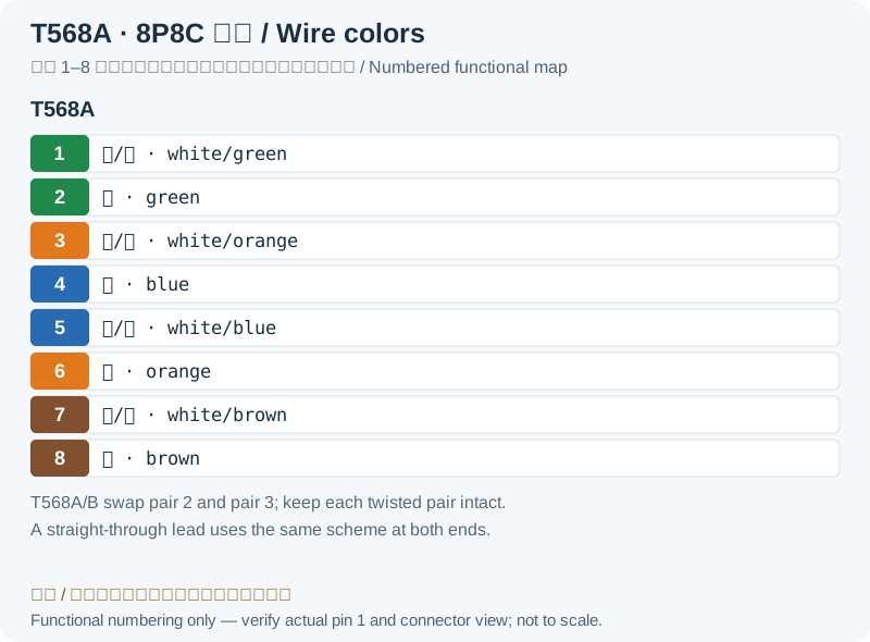
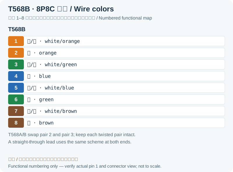
| Pin | T568A | T568B | 10/100 mode B | 10/100 mode A | 1000 mode B | 1000 mode A | ||||
|---|---|---|---|---|---|---|---|---|---|---|
| 1 |  white/green |  white/orange | Rx + | Rx + | DC + | TxRx A + | TxRx A + | DC + | ||
| 2 |  green |  orange | Rx - | Rx - | DC + | TxRx A - | TxRx A - | DC + | ||
| 3 | white/orange | white/green | Tx + | Tx + | DC - | TxRx B + | TxRx B + | DC - | ||
| 4 |  blue | blue | DC + | TxRx C + | DC + | TxRx C + | ||||
| 5 |  white/blue | white/blue | DC + | TxRx C - | DC + | TxRx C - | ||||
| 6 | orange | green | Tx - | Tx - | DC - | TxRx B - | TxRx B - | DC - | ||
| 7 |  white/brown | white/brown | DC - | TxRx D + | DC - | TxRx D + | ||||
| 8 |  brown | brown | DC - | TxRx D - | DC - | TxRx D - | ||||
Legacy source notes and applicability
These notes retain the legacy record. For corrected facts and applicability, use this page’s quick answer, scope and visible table corrections.
802.3af A/B Standards
white/green
white/orange
green
orange
blue
white/blue
white/brown
brown
Pinout from the power sourcing equipment perspective.
Frequently asked questions
Is Mode A the same as T568A?
No. Mode A/B selects PoE contact groups; T568A/B assigns cable-pair colors to contacts 1–8. They are different classifications.
Does four-pair power prevent Gigabit data?
Sharing pairs does not inherently exclude data. Standards-based PoE applies common-mode power through transformer center taps or equivalent circuits while data is differential. The port must still support the required speed and power type.
Why can a PD not assume 90 W from a 90 W PSE rating?
The cable has an allocated loss budget, and classification and total budgets also constrain power. Use the allocation at the PD interface rather than substituting the PSE label.
Related tools and references
Sources and verification
- Texas Instruments: TPS2373, Table 6 limits and powered pair sets
- Cisco: 802.3bt types, classes, detection and single/dual-signature PDs
- Microchip: normal guaranteed PoE power versus Extended Power conditions
Legacy baseline: the Electrodoc Pro 5.2 data package. Raw records are retained and checked factual corrections are shown explicitly.