PCB TOOLS / Electronics reference
PC Peripheral Power Pinouts: Molex, Floppy, SATA and 3/4-Wire Fans
Look up peripheral, floppy, SATA/Slimline/Micro power and fan power/tachometer/PWM contacts. Includes SATA P3’s optional PWDIS role and conditions on voltage, colors and compatibility.
Quick answer
Traditional peripheral contacts 1/2/3/4 are +12 V, ground, ground and +5 V. The small floppy connector instead uses +5 V, ground, ground and +12 V; four contacts do not make them interchangeable. A common 12 V four-wire fan uses 1 ground, 2 supply, 3 tachometer and 4 PWM. Distinguish legacy 3.3 V on SATA P3 from optional PWDIS.
Scope
Seven legacy tables cover 15-contact SATA, the six-contact Slimline power segment and the older Micro SATA power segment; these are different connectors. A mechanical key is not a contact. Colors are only aids, particularly on a modular PSU’s proprietary side. Diagrams use functional numbering; obtain viewing direction, current ratings and keying from the actual component drawing.
Reading example
For a +5 V load, use contact 4/red on the traditional large peripheral connector but contact 1/red on the small floppy connector. If a SATA drive implements P3 PWDIS, a legacy harness holding P3 at 3.3 V may prevent startup. Check the drive and harness specifications rather than treating P3 as an unconditional supply input.
Legacy tables with visible corrections
Disk drive connector (Molex 8981)
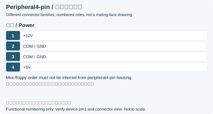
| Pin | Color | Function |
|---|---|---|
| 1 | Yellow | +12 V |
| 2 | Black | Ground |
| 3 | Black | Ground |
| 4 | Red | +5 V |
Floppy Power (Mini-Molex)
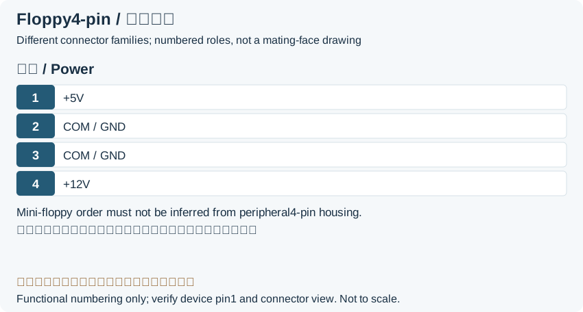
| Pin | Color | Function |
|---|---|---|
| 1 | Red | +5 V |
| 2 | Black | Ground |
| 3 | Black | Ground |
| 4 | Yellow | +12 V |
Serial ATA Power connector
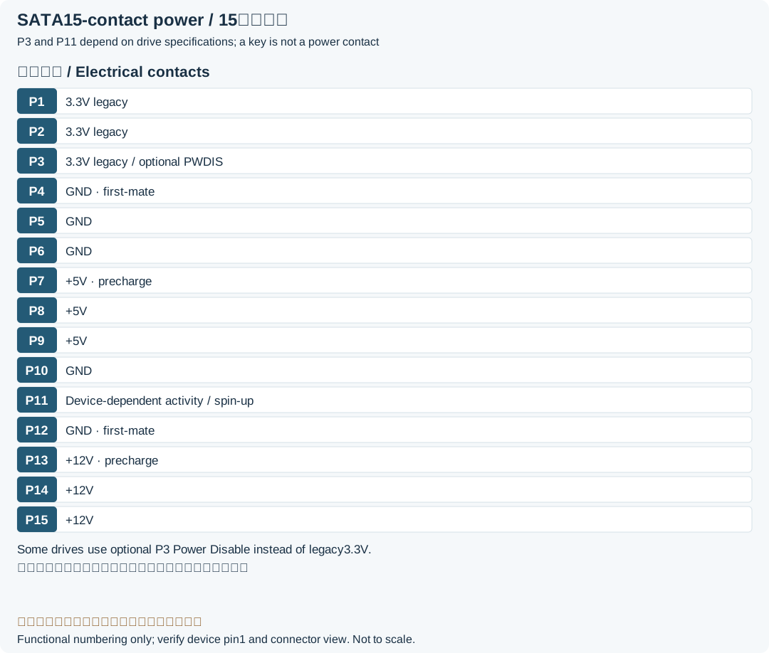
| Pin | Color | Function |
|---|---|---|
| - | Coding notch | |
| 1 | Orange | +3.3 V |
| 2 | Orange | +3.3 V |
| 3 | Orange | Legacy +3.3 V; optional Power Disable on supporting devicesLegacy record: “+3.3 V”. The source +3.3 V omits optional PWDIS. The cited Seagate manual assigns P3 to PWRDIS; verify the actual drive rather than assuming a supply. |
| 4 | Black | Ground |
| 5 | Black | Ground |
| 6 | Black | Ground |
| 7 | Red | +5 V |
| 8 | Red | +5 V |
| 9 | Red | +5 V |
| 10 | Black | Ground |
| 11 | Grey | Ground or activity/deferred-spin function (model-dependent)Legacy record: “Ground/Optional”. The source Ground/Optional lacks conditions. In the Seagate example, grounding P11 affects deferred spin. |
| 12 | Black | Ground |
| 13 | Yellow | +12 V |
| 14 | Yellow | +12 V |
| 15 | Yellow | +12 V |
Slimline SATA connector (power segment)
| Pin | Color | Function |
|---|---|---|
| - | Coding notch | |
| 1 | Grey | Device presence |
| 2 | Red | +5 V |
| 3 | Red | +5 V |
| 4 | Grey | Manufacturing diagnostic |
| 5 | Black | Ground |
| 6 | Black | Ground |
Micro SATA connector (power segment)
| Pin | Color | Function |
|---|---|---|
| 1 | Orange | +3.3 V |
| 2 | Orange | +3.3 V |
| 3 | Black | Ground |
| 4 | Black | Ground |
| 5 | Red | +5 V |
| 6 | Red | +5 V |
| 7 | Grey | Reserved |
| - | Coding notch | |
| 8 | Grey | Vendor specific |
| 9 | Grey |
3 and 4-Pin Fan Connector
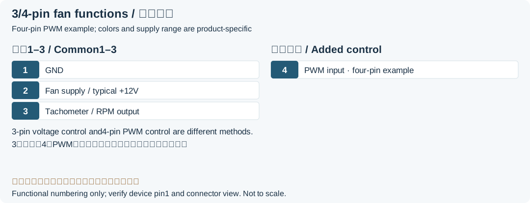
| Pin | Color | Function |
|---|---|---|
| 1 | Black | Ground |
| 2 | Red | +12 V (or variable) |
| 3 | Yellow | Tachometric Signal |
| Pin | Color | Alt. Color | Function |
|---|---|---|---|
| 1 | Black | Black | Ground |
| 2 | Yellow | Red | +12 V |
| 3 | Green | Yellow | Sense Signal |
| 4 | Blue | Blue | PWM Control |
Legacy source notes and applicability
These notes retain the legacy record. For corrected facts and applicability, use this page’s quick answer, scope and visible table corrections.
Floppy Power (Mini-Molex)
Serial ATA Power connector
Pins 1, 2, and 3 are optional.
Pins 3, 7, 13 and Ground are longer on the plug so they connect first.
Pin 11 can be used for activity indication, staggered spin-up, both, or nothing.
Slimline SATA connector (power segment)
Micro SATA connector (power segment)
3 and 4-Pin Fan Connector
Note: 3-pin and 4-pin versions are compatible: 4-pin can be plugged into 3-pin headers (and vice versa), but lose its fan speed control.
Frequently asked questions
Is fan contact 3 a power input?
In the common PC interface shown, contact 3 is tachometer output, 4 is PWM control and power is contact 2. Check the fan specification for signal levels, open-collector/drain behavior and pulses per revolution.
Can I omit arbitrary SATA contacts carrying the same voltage?
The table does not justify doing so. Parallel contacts, mating sequence, returns and optional P3/P11 functions have conditions. The drive and connector-system specifications determine whether a supply rail can be omitted.
Related tools and references
Sources and verification
- Intel: desktop PSU guide, Tables 4-2/4-3 peripheral and floppy pinouts
- Seagate: AI IoT SATA manual, Table 26 P3/P11 and mating stages
- Noctua: example 12 V four-wire fan functions and colors
- Noctua: 3/4-pin connections and speed-control conditions
- SATA-IO: historical Slimline P4 MD/DA proposal
- SATA-IO: historical Micro SATA P7 activity proposal (not a final specification)
Legacy baseline: the Electrodoc Pro 5.2 data package. Raw records are retained and checked factual corrections are shown explicitly.