PCB TOOLS / Electronics reference
ATA and SATA Pinouts: 40/44-Pin PATA, 7-Contact SATA/eSATA and eSATAp
Look up ATA and SATA contacts while distinguishing 40/44-pin parallel interfaces, seven serial contacts, mechanical keys and separate power segments. Includes explicit qualifications for PATA keys, signal names and legacy eSATAp power.
Quick answer
Standard SATA/eSATA data interfaces have seven electrical contacts; the mechanical key is not contact 8. Common 40-pin PATA does not power the drive through the data cable. A 44-pin 2.5-inch PATA interface adds supply contacts 41/42 and return 43. Position 20 is a key: do not apply power based on the source VCC wording.
Scope
The PATA table retains positions 1–44 to cover both forms, but different pitch and mechanics prevent direct interchange. SATA A/B directions here use the host perspective and reverse at the device. SATA, eSATA and eSATAp also have different mechanical interfaces. eSATAp is a legacy combined USB/eSATA implementation; confirm 5 V/12 V capability and extra contacts against the actual port and cable. All diagrams show functional numbering without guessing a mating view.
Reading example
On a normal SATA drive the seven-contact segment carries data and the 15-contact segment carries power. Never wire the data key labeled 8 in the legacy table as a supply. For 44-pin PATA, 41/42 are supply positions, 43 is ground and 20 is the key. An eSATAp device requiring 12 V needs an explicitly compatible 12 V port/cable combination, not merely an eSATAp label.
Legacy tables with visible corrections
Parallel ATA / EIDE
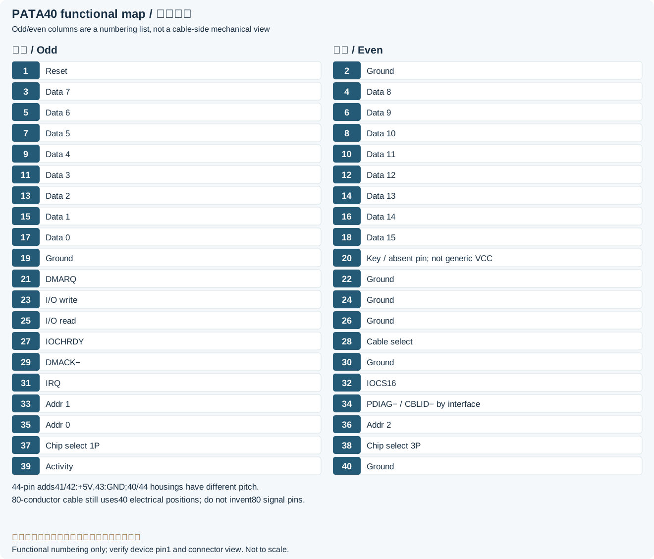
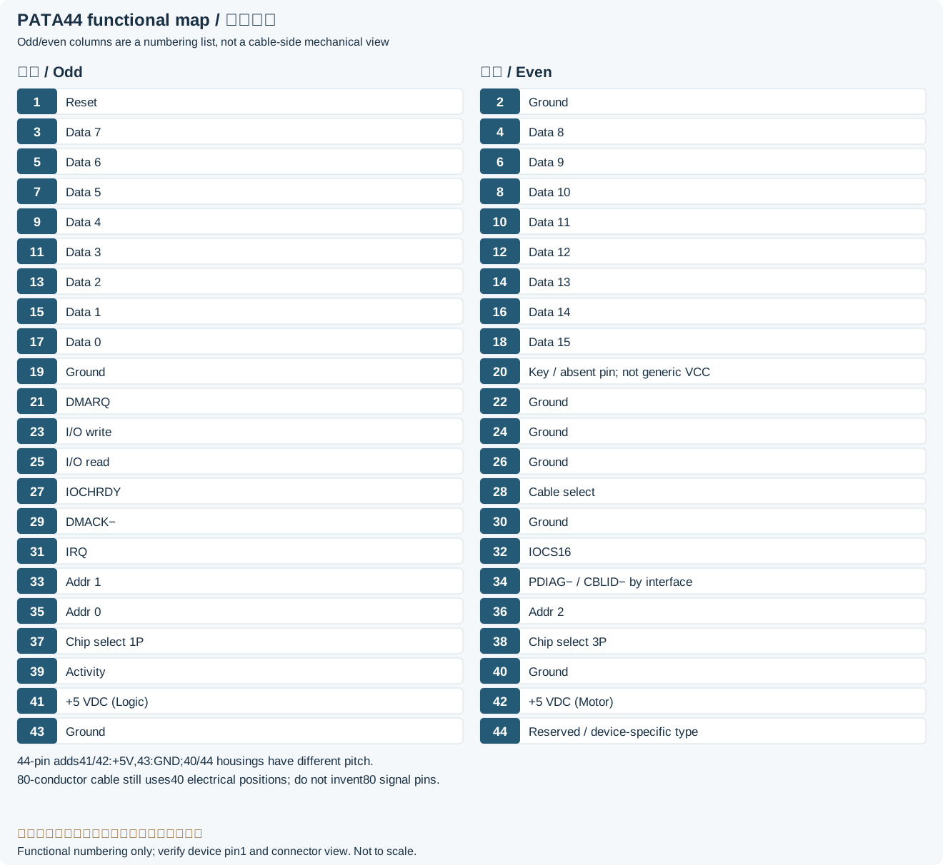
| Pin | Function | Pin | Function |
|---|---|---|---|
| 1 | Reset | 2 | Ground |
| 3 | Data 7 | 4 | Data 8 |
| 5 | Data 6 | 6 | Data 9 |
| 7 | Data 5 | 8 | Data 10 |
| 9 | Data 4 | 10 | Data 11 |
| 11 | Data 3 | 12 | Data 12 |
| 13 | Data 2 | 14 | Data 13 |
| 15 | Data 1 | 16 | Data 14 |
| 17 | Data 0 | 18 | Data 15 |
| 19 | Ground | 20 | Mechanical key/removed pin; not a universal VCC inputLegacy record: “Key or VCC_in”. The source Key or VCC_in mixes in a non-universal supply role. Seagate marks position 20 removed/key; do not use that wording to energize a standard key position. |
| 21 | DMARQ (DMA request)Legacy record: “DDRQ”. Source DDRQ is an incorrect/non-standard abbreviation; Seagate labels contact 21 DMARQ. | 22 | Ground |
| 23 | I/O write | 24 | Ground |
| 25 | I/O read | 26 | Ground |
| 27 | IOCHRDY | 28 | Cable select |
| 29 | DMACK− (DMA acknowledge, active low)Legacy record: “DDACK”. Source DDACK omits M and active-low notation; the interface diagram labels contact 29 DMACK−. | 30 | Ground |
| 31 | IRQ | 32 | IOCS16 |
| 33 | Addr 1 | 34 | PDIAG− / CBLID− (interface/cable dependent)Legacy record: “GPIO_DMA66_Detect”. Source GPIO_DMA66_Detect is a platform implementation name, not the general ATA contact name. Seagate’s older diagram uses PDIAG−; later cable-detection use depends on the specification. |
| 35 | Addr 0 | 36 | Addr 2 |
| 37 | Chip select 1P | 38 | Chip select 3P |
| 39 | Activity | 40 | Ground |
| 41 | +5 VDC (Logic) | 42 | +5 VDC (Motor) |
| 43 | Ground | 44 | Reserved or device-defined (not universally Type=0)Legacy record: “Type (0=ATA)”. Source Type (0=ATA) is not universal for 44-pin devices; the cited Seagate diagram marks 44 Reserved. |
Serial ATA
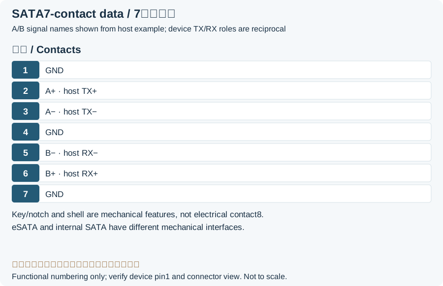
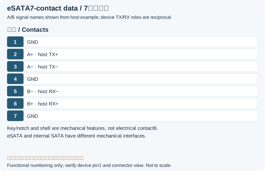
| Pin | Function |
|---|---|
| 1 | Ground |
| 2 | A+ (host transmit / device receive)Legacy record: “A+ (transmit)”. Source transmit omits the endpoint; direction must be interpreted relative to host or device. |
| 3 | A− (host transmit / device receive)Legacy record: “A- (transmit)”. The source transmit label is interpreted from the host perspective, not as transmit at the device too. |
| 4 | Ground |
| 5 | B− (host receive / device transmit)Legacy record: “B- (receive)”. Source receive omits the endpoint; host/device roles are stated here. |
| 6 | B+ (host receive / device transmit)Legacy record: “B+ (receive)”. Source receive omits the endpoint; host/device roles are stated here. |
| 7 | Ground |
| Not a contactLegacy record: “8”. Source number 8 labels the adjacent Coding notch. SATA/eSATA data has seven electrical contacts. | Coding notch |
eSATAp (Power eSATA)
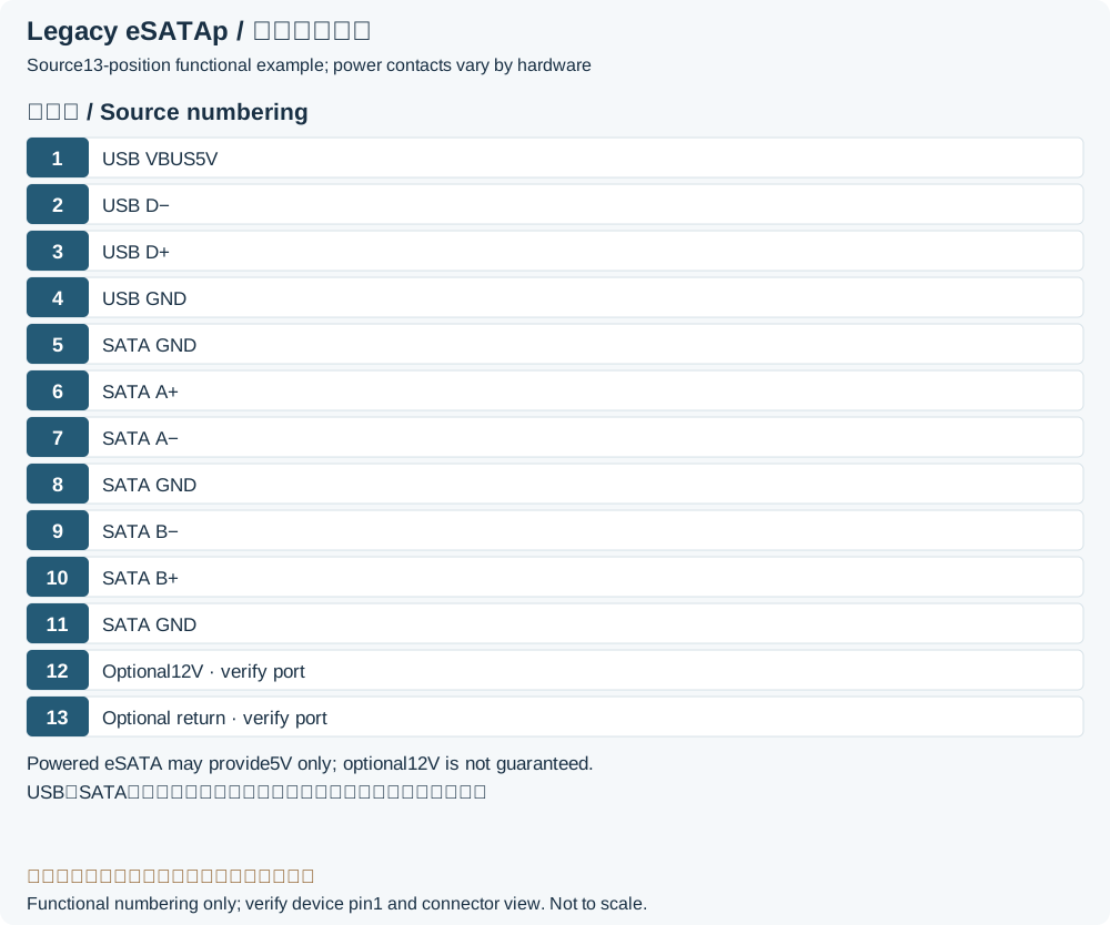
| Pin | Function |
|---|---|
| 1 | USB VBus (5V) |
| 2 | USB D- |
| 3 | USB D+ |
| 4 | USB Ground |
| 5 | Ground |
| 6 | A+ |
| 7 | A- |
| 8 | Ground |
| 9 | B- |
| 10 | B+ |
| 11 | Ground |
| 12 | Optional 12 V (supporting eSATApd port/cable only)Legacy record: “VBus (12V)”. Source VBus (12V) does not guarantee 12 V on every eSATAp port. Delock’s example explicitly requires a compatible 5/12 V port. |
| 13 | Ground |
Legacy source notes and applicability
These notes retain the legacy record. For corrected facts and applicability, use this page’s quick answer, scope and visible table corrections.
ATAPI-44 connector (used on 2.5" devices) has 4 additional pins used for power.
Pins 1-40 are the same as the 40 pin connector, but the spacing between pins is smaller and they are not physically compatible.
80-wire cables has the same pinout as 40-conductor cables. Internally the connectors are different: the 80-wire cable provides one ground wire to each signal wire.
Cables usually come with three differently colored connectors (blue=controller, black=master drive, gray=slave drive)
Serial ATA
7 pin SATA plug
eSATAp (Power eSATA)
Some devices do not have +12V power available (pin 12-13)
Frequently asked questions
Does a SATA data connector have pin 8?
There is no eighth electrical contact. The final source row describes a mechanical key; its displayed number is corrected to not a contact, with original 8 retained in the correction note.
Does host Tx connect to device Tx?
The endpoint roles differ. The host transmit pair connects to the device receive pair, and vice versa. This page describes A+/A− and B−/B+ from the host perspective instead of applying the same Tx label at both ends.
Does eSATA itself power a drive?
Ordinary eSATA is a data interface. eSATAp is a legacy combined variant with USB/power contacts and does not guarantee 12 V on every port. Check the specific port and cable.
Related tools and references
Sources and verification
- Seagate: Marathon ATA manual, 44-pin connector and Figure 6 signals
- Seagate: SATA seven-contact and separate power-segment definitions
- TI VAYU EVM schematic: sheet 37 host-side SATA A/B direction
- Delock: example eSATApd 5/12 V device and port requirements
Legacy baseline: the Electrodoc Pro 5.2 data package. Raw records are retained and checked factual corrections are shown explicitly.