PCB TOOLS / Electronics reference
PC parallel and Centronics pinout
Compare legacy PC 25-pin parallel and 36-pin printer signals, directions and register bits.
Quick answer
D0–D7 use pins 2–9 on both forms; DB25 pin 1 is strobe, 10 acknowledge, and 18–25 signal returns.
Scope
Directions and registers retain the legacy PC context, not all EPP/ECP modes or printer implementations; diagrams do not establish mechanical view.
Reading example
For Data3, use pin 5 on either form; Error is DB25 pin 15 versus36-pin pin 32.
Legacy tables with visible corrections
Parallel/Centronics port
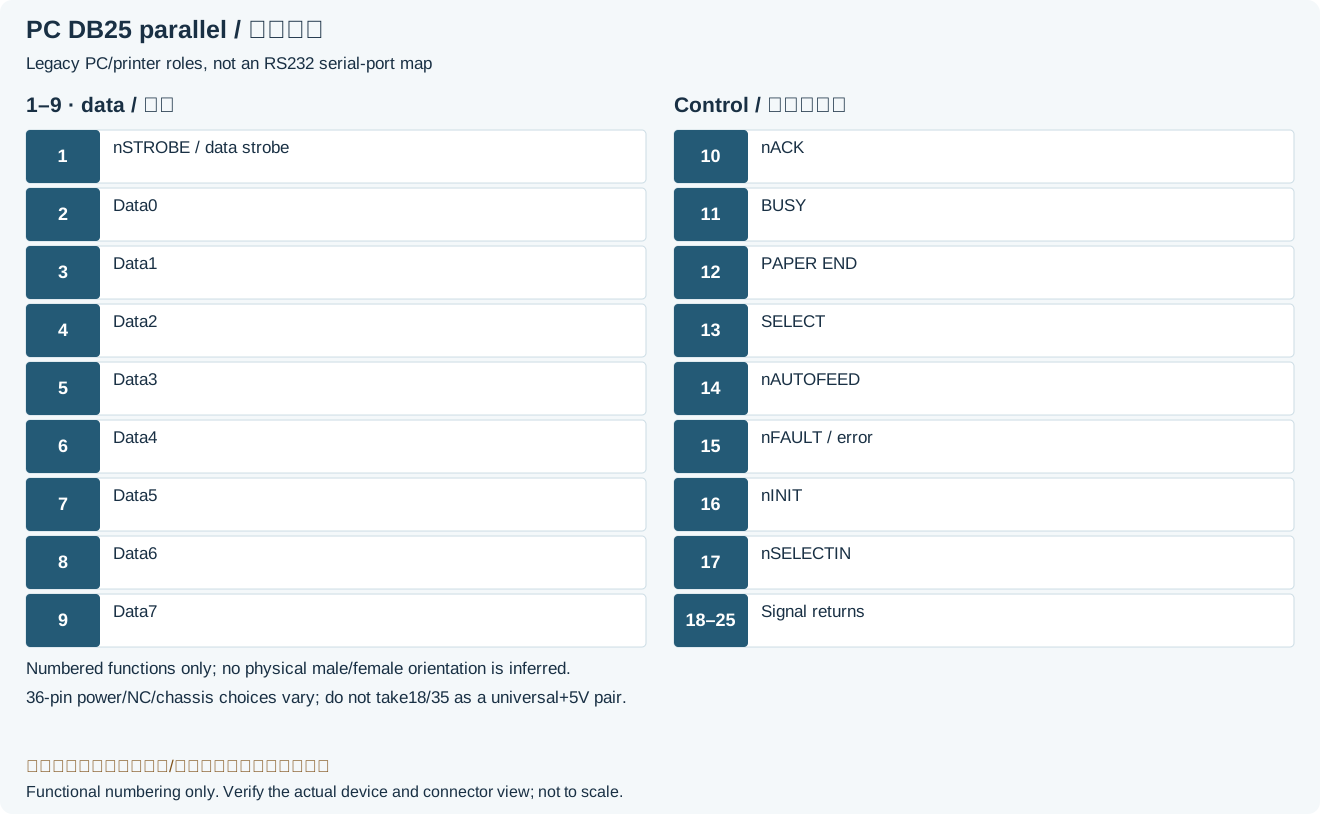
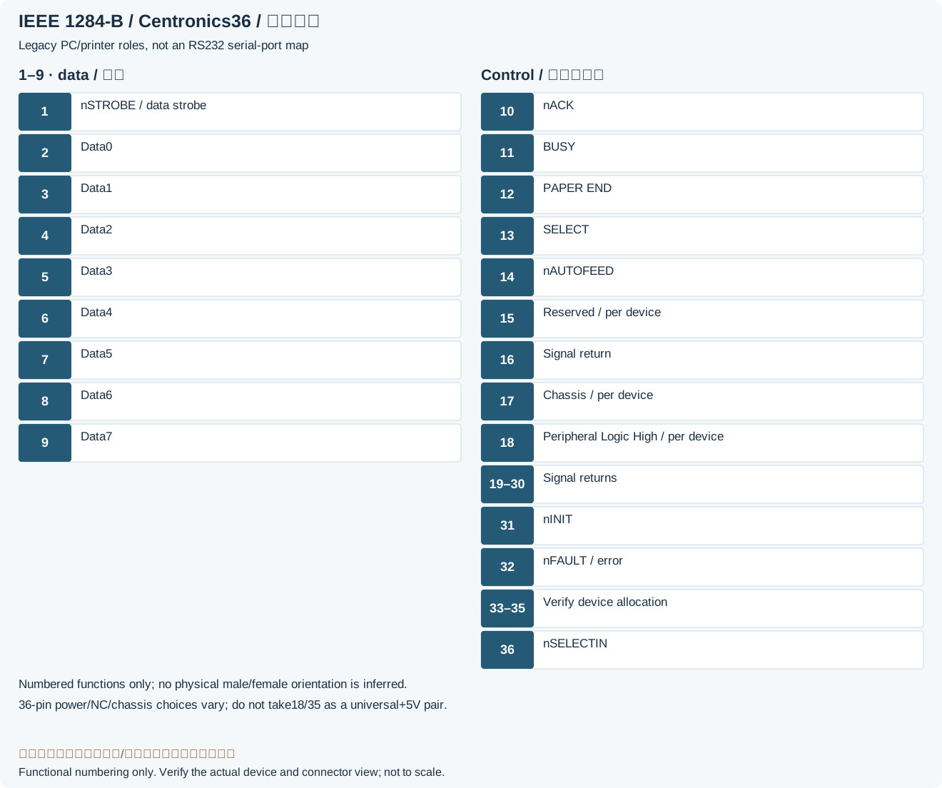
| Pin (25 pin) | Pin (36 pin) | Signal name | Direct. | Register bit |
|---|---|---|---|---|
| 1 | 1 | Strobe | In/Out | Control-0 |
| 2 | 2 | Data0 | Out | Data-0 |
| 3 | 3 | Data1 | Out | Data-1 |
| 4 | 4 | Data2 | Out | Data-2 |
| 5 | 5 | Data3 | Out | Data-3 |
| 6 | 6 | Data4 | Out | Data-4 |
| 7 | 7 | Data5 | Out | Data-5 |
| 8 | 8 | Data6 | Out | Data-6 |
| 9 | 9 | Data7 | Out | Data-7 |
| 10 | 10 | Ack | In | Status-6 |
| 11 | 11 | Busy | In | Status-7 |
| 12 | 12 | Paper-Out | In | Status-5 |
| 13 | 13 | Select | In | Status-4 |
| 14 | 14 | Linefeed | In/Out | Control-1 |
| 15 | 32 | Error | In | Status-3 |
| 16 | 31 | Reset | In/Out | Control-2 |
| 17 | 36 | Select-Printer | In/Out | Control-3 |
| - | 18,35 | IEEE 1284-B: 18 Peripheral Logic High; 35 undefined, verify implementationLegacy record: “+5V”. onsemi Table 6 lists18 Peripheral Logic High and 35 undefined, not a universal+5V power pair. | - | - |
| - | 15,34 | n.c. | - | - |
| 18-25 | 16, 19–30 logic/signal returns; 17 chassis; 33 undefinedLegacy record: “16,17, 19-30, 33”. onsemi Table 6 distinguishes logic return 16, chassis17, signal returns 19–30 and undefined33. | Ground | - | - |
Legacy source notes and applicability
These notes retain the legacy record. For corrected facts and applicability, use this page’s quick answer, scope and visible table corrections.
Frequently asked questions
Can a 25-pin parallel port connect directly to RS232?
No.The same shell does not imply matching signals, levels or allocation.
Why are there two separate functional diagrams?
PC 25-pin and printer36-pin control positions differ; both drawings use parallel functions rather than serial-port assignments.
Related tools and references
Sources and verification
Legacy baseline: the Electrodoc Pro 5.2 data package. Raw records are retained and checked factual corrections are shown explicitly.