PCB TOOLS / PINOUT & INTERFACE REFERENCE
Character LCD Pinout: HD44780-Compatible 16-Pin Interface
Identify power, contrast, control, eight-bit data and backlight contacts on a common character LCD, including the four data lines used in four-bit mode.
Quick answer
In this common 16-contact assignment, 1 is VSS, 2 VDD, 3 contrast, 4/5/6 RS, R/W and E, 7–14 DB0–DB7 and 15/16 backlight LED_A/LED_K. Four-bit mode uses DB4–DB7, contacts 11–14 in this table.
Scope
Applies to the common HD44780 instruction-compatible parallel module shown here. Instruction compatibility does not guarantee identical contact order, voltages, backlight circuitry or timing. This is neither the bare-controller package pinout nor an I²C backpack map.
Reading example
For four-bit writes, connect RS, E and DB4–DB7 according to the module datasheet; hold R/W low for write-only operation when permitted. Perform the module’s four-bit initialization sequence: wiring four data lines alone does not select the mode.
Interfaces, pinouts and technical reference
Character LCD pinout
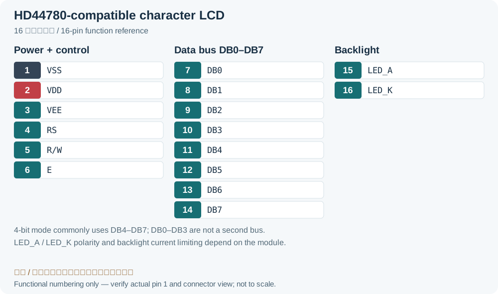
| Pin | Name | Description |
|---|---|---|
| 1 | VSS | Ground (0V) |
| 2 | VDD | Positive supply voltage |
| 3 | VEE | Contrast adjustment |
| 4 | RS | Register select signal |
| 5 | R/W | Read/Write signal |
| 6 | E | Enable signal |
| 7 | DB0 | Data bus line 0 |
| 8 | DB1 | Data bus line 1 |
| 9 | DB2 | Data bus line 2 |
| 10 | DB3 | Data bus line 3 |
| 11 | DB4 | Data bus line 4 |
| 12 | DB5 | Data bus line 5 |
| 13 | DB6 | Data bus line 6 |
| 14 | DB7 | Data bus line 7 |
| 15 | LED_A | LED power supply (+V) |
| 16 | LED_K | LED power supply (0V) |
Legacy source notes and applicability
These notes retain the legacy record. For corrected facts and applicability, use this page’s quick answer, scope and visible table corrections.
HITACHI HD44780 compatible
Frequently asked questions
Are DB0–DB3 needed in four-bit mode?
Four-bit transfers use DB4–DB7 in two steps. DB0–DB3 do not carry data in that mode. Follow the specific module’s instructions for unused pins and power-on initialization.
What should I check if the backlight works but characters do not appear?
The backlight and display logic are separate circuits. Check VSS/VDD, contrast, contact orientation, RS/E, data wiring and initialization timing. A lit backlight does not demonstrate a working bus.
Related tools and references
Sources and verification
- Newhaven Display: NHD-0216K1Z-FL-YBW pin and electrical specifications
- Newhaven Display: character LCD four-bit interface example
Legacy baseline: the Electrodoc Pro 5.2 data package. Raw records are retained and checked factual corrections are shown explicitly.