PCB TOOLS / PINOUT & INTERFACE REFERENCE
PIC ICSP and AVR ISP Programming Pinouts
Compare PIC six-wire ICSP with classic AVR 6/10-pin ISP. Similar names do not make connectors or voltages compatible; identify the device, programmer and target supply first.
Quick answer
PIC ICSP commonly uses VPP/MCLR, VDD, VSS, PGD, PGC and an auxiliary pin. Classic AVR ISP uses MISO, MOSI, SCK, RESET, target-voltage reference and GND. PIC VPP and VDD must follow the device specification, not universal 13.5 V and 5 V settings.
Scope
Retains legacy PICkit-style 6-pin, legacy RJ-12 ICSP context and classic AVR SPI ISP 6/10-pin arrangements. This is not universal for all modern PIC/AVR devices: use the appropriate manual for UPDI, PDI, TPI, debugWIRE or newer programmers. RJ-12 artwork is a signal correspondence only; the source does not establish enough view information to infer mirrored plug/socket orientation.
Reading example
For a confirmed classic 6-pin AVR ISP target, check 1=MISO, 2=target voltage, 3=SCK, 4=MOSI, 5=RESET and 6=GND. Uno R3 main ICSP uses these signals, but its pin-1 marking still establishes orientation. The same numbers on a PIC header mean different signals and are not interchangeable.
Interfaces, pinouts and technical reference
Microchip PIC ICSP
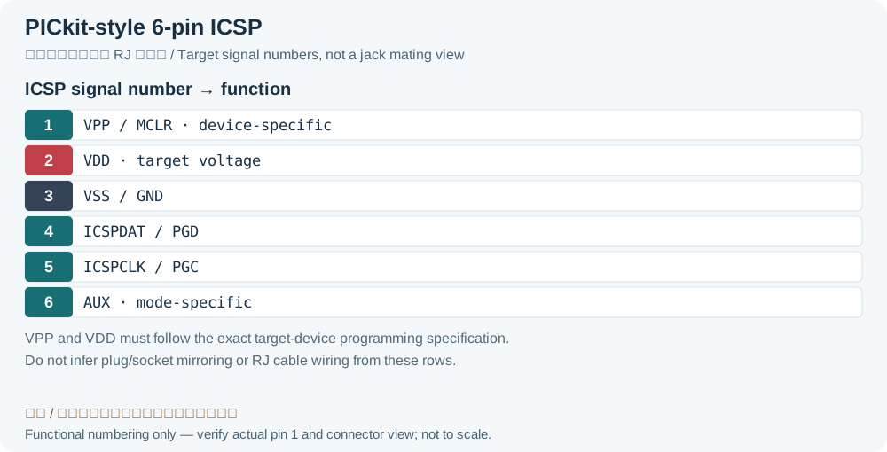
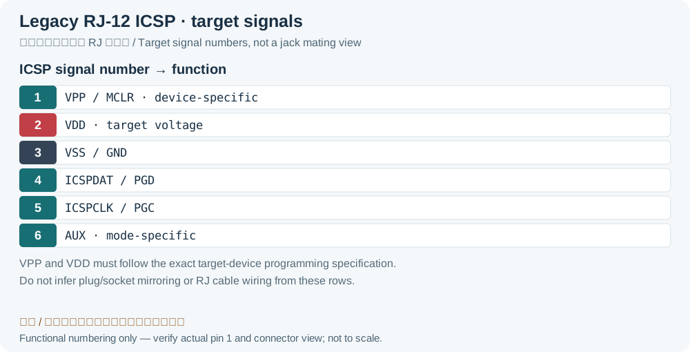
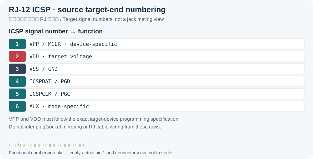
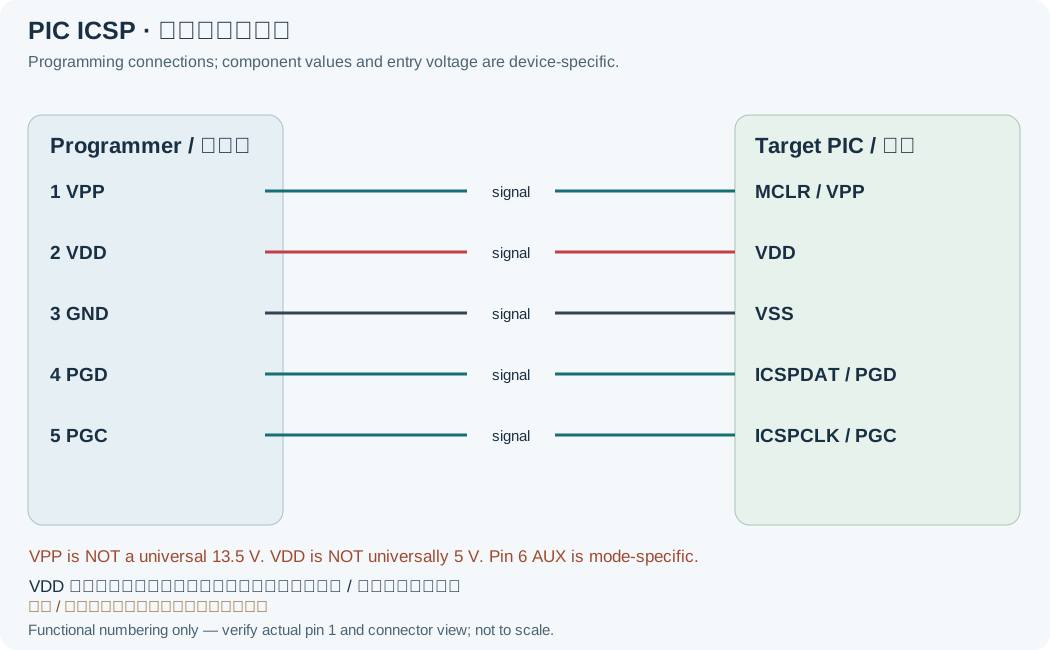
| Pin | Name | Description |
|---|---|---|
| 1 | VPP/MCLR | Programming-entry/reset voltage per device specification; 13.5 V is only a legacy-device exampleLegacy record: “Programming mode voltage (can be as high as 13.5V)”. Prevents interpreting the source 13.5 V example as a universal PIC programming voltage. |
| 2 | VDD (target voltage)Legacy record: “+5V”. Source +5V is not universal for PIC; supply/sense behavior depends on device and programmer. | Target supply voltage |
| 3 | VSS/GND | Ground reference |
| 4 | ICSPDAT/PGD | Serial Data line |
| 5 | ICSPCLK/PGC | Serial Clock line |
| 6 | Auxiliary | n/c |
Atmel AVR ISP
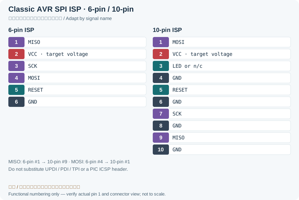
| Pin | Name | Description |
|---|---|---|
| 1 | MISO | Master In, Slave Out |
| 2 | VCC (target voltage)Legacy record: “+5V”. Source +5V applies to some legacy AVR targets, not every AVR voltage. | Target supply voltage |
| 3 | SCK | Serial data Clock |
| 4 | MOSI | Master Out, Slave In |
| 5 | RESET | Target Reset |
| 6 | GND | Signal ground |
| Pin | Name | Description |
|---|---|---|
| 1 | MOSI | Master Out, Slave In |
| 2 | VCC (target voltage)Legacy record: “+5V”. As in the 6-pin table, the fixed +5V label is clarified as target voltage. | Target supply voltage |
| 3 | LED or n/c | Programming in progress |
| 4 | GND | Signal ground |
| 5 | RESET | Target Reset |
| 6 | GND | Signal ground |
| 7 | SCK | Serial data Clock |
| 8 | GND | Signal ground |
| 9 | MISO | Master In, Slave Out |
| 10 | GND | Signal ground |
Legacy source notes and applicability
These notes retain the legacy record. For corrected facts and applicability, use this page’s quick answer, scope and visible table corrections.
Atmel AVR ISP
Frequently asked questions
Can I apply 13.5 V to every PIC using this table?
No. VPP is a programming-entry condition specified for the exact device and supported programmer. Low-voltage programming and high-voltage entry are not interchangeable; do not apply high voltage without that specification.
Do 6-pin and 10-pin AVR ISP use the same pin numbers?
No. MISO is pin 1 on the 6-pin header and pin 9 on this 10-pin layout; MOSI is pin 4 and pin 1 respectively. Adapt by signal name and verify key/pin 1 rather than connecting matching positions.
Can a programmer identify an unpowered target using only signal wires?
A valid target supply and voltage sense are normally required. Do not assume signal wires safely power the device. Select target or programmer power according to the manual and share ground.
Related tools and references
Sources and verification
- Microchip: PICkit 5 signals, power and ICSP connections
- Microchip: legacy PICkit 2 and device programming specifications
- Microchip: ICSP target circuitry and voltage sensing
- Arduino Uno R3 official classic AVR ICSP mapping
- Microchip / Atmel: STK500 classic AVR ISP 6/10-pin headers
Legacy baseline: the Electrodoc Pro 5.2 data package. Raw records are retained and checked factual corrections are shown explicitly.