PCB TOOLS / Electronics reference
Circuit Symbol Reference: 121 Component Entries
Look up passive components, diodes, transistors, logic gates, switches, relays and tubes by component name. Original drawings identify terminal functions and distinguish common notation, selected device variants and functional equivalents.
Quick answer
Identify terminals and function before interpreting drawing style. K is the diode cathode; BJT emitter arrows point out for NPN and in for PNP. JFET gate arrows and MOSFET body arrows are different conventions. A small logic bubble denotes inversion; a filled junction dot denotes a wire connection. A schematic symbol is not a package pinout.
Scope
This reference follows 121 source rows, including legacy RF devices and vacuum tubes; it is not a complete component catalogue. All artwork is original educational drawing. IEC-style rectangular and ANSI-style zigzag resistors/logic shapes are identified; other variants or functional equivalents are labeled separately. No IEC 60617 or IEEE conformity certification is claimed. Terminal names do not specify package numbers, ratings or connector orientation.
Reading example
For an NPN, locate B, C and E and check that the E-branch arrow points outward; it does not mark package pin 1. In the single-gate MOSFET example, check the insulated gate, broken enhancement channel and N-channel body diode from S to D. P-channel, depletion-mode or four-terminal devices require their own data-sheet symbol.
Checked reference tables
| Item | Interpretation |
|---|---|
| Independent / dependent source | Circle / diamond; also check +/− and current arrow |
| Potentiometer / rheostat / RTD | Three-terminal divider / two-terminal adjustable resistance / temperature-sensing resistor |
| SPST / SPDT / DPST / DPDT | Poles count independent circuits; throws count selectable contacts per pole |
| Symbol / package | Terminal function is not a package number or pad position |
| Chassis / earth / signal reference | Distinct functions; bonding depends on the equipment design, and a symbol does not certify PE wiring |
Legacy tables with visible corrections
| COMPONENT | SYMBOLS | |
|---|---|---|
| Ammeter | 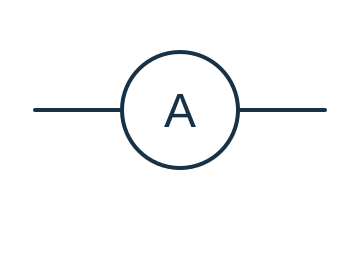 | |
| And Gate | 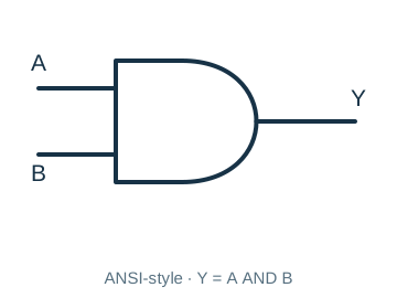 | |
| Antenna, Balanced | 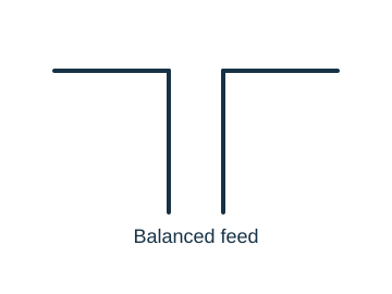 | |
| Antenna, General | 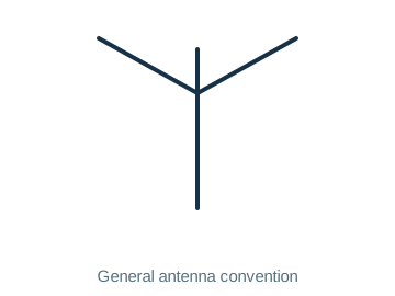 | 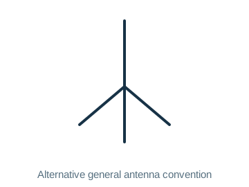 |
| Antenna, Loop, Shielded | 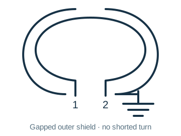 | |
| Antenna, Loop, Unshielded | 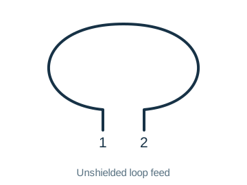 | |
| Battery | 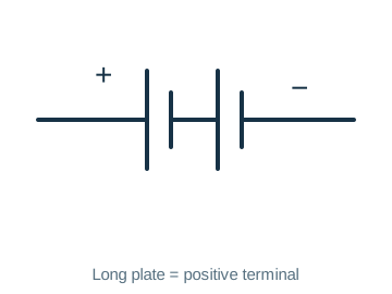 | |
| Battery Cell | 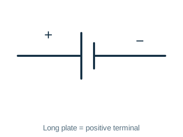 | |
| Capacitor, Feedthrough | 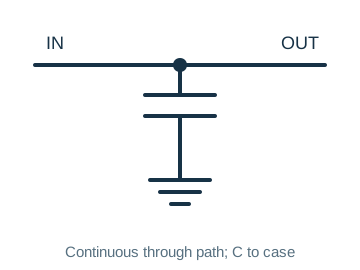 | |
| Capacitor, Fixed, Nonpolarized | 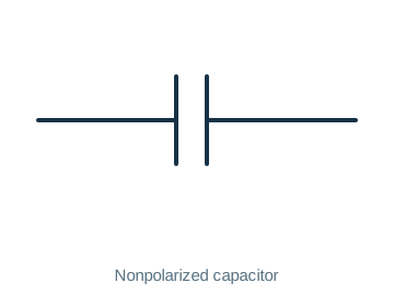 | |
| Capacitor, Fixed, Polarized | 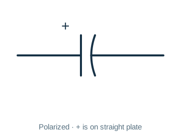 | |
| Capacitor, Ganged, Variable | 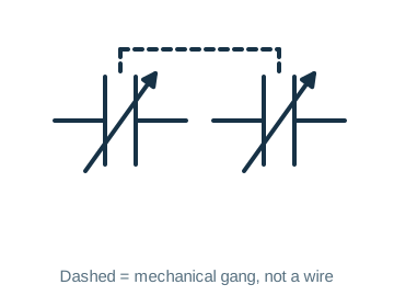 | |
| Capacitor, General | 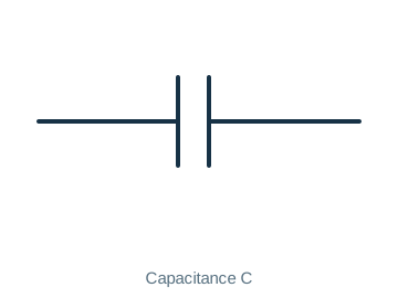 | |
| Capacitor, Variable, Single | 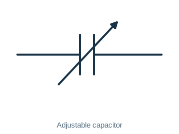 | |
| Capacitor, Variable, Split-Stator | 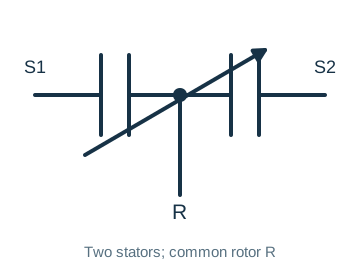 | |
| Cathode, Cold | 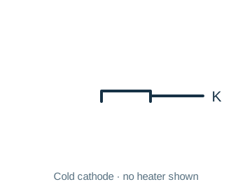 | |
| Cathode, Directly Heated | 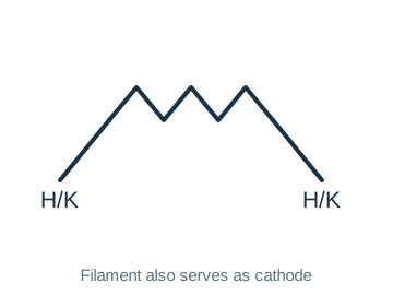 | |
| Cathode, Indirectly Heated | 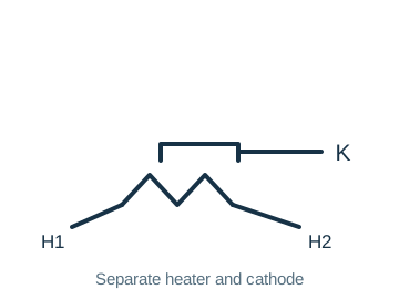 | 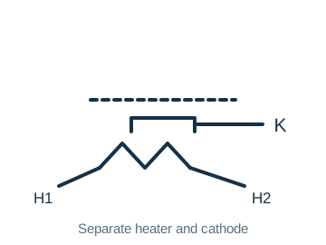 |
| Cavity Resonator | 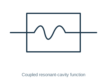 | |
| Circuit Breaker | 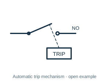 | |
| Coaxial Cable | 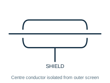 | 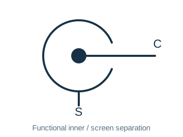 |
| Crystal, Piezoelectric | 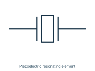 | |
| Delay Line | 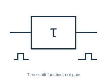 | 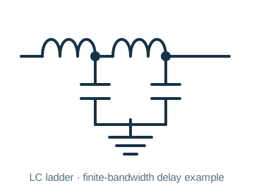 |
| Diode | 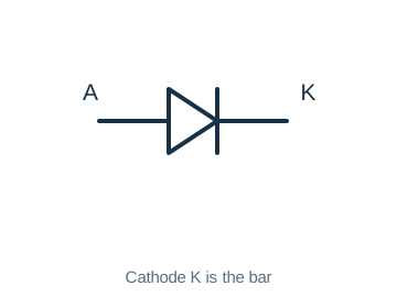 | |
| Diode, Gunn | 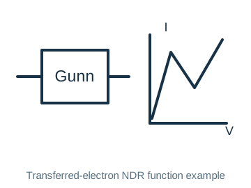 | |
| Diode, Light-Emitting | 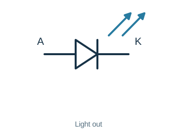 | |
| Diode, Photosensitive | 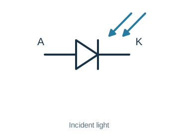 | |
| Diode, Photovoltaic | 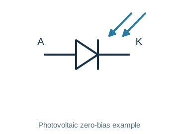 | |
| Diode, Varicap | 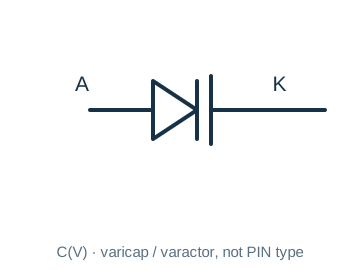 | |
| Diode, Schottky | 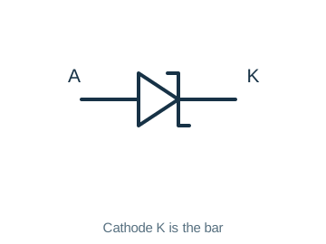 | |
| Diode, Varactor | 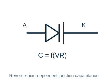 | |
| Diode, Zener | 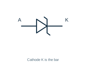 | |
| Directional Coupler | 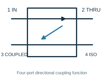 | 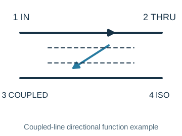 |
| Exclusive-Or Gate | 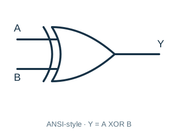 | |
| Female Contact, General | 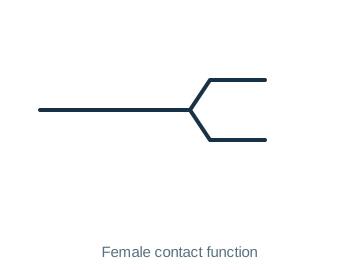 | |
| Ferrite Bead | 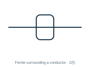 | 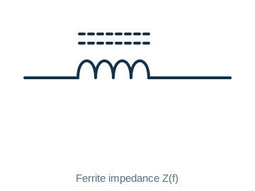 |
| Fuse | 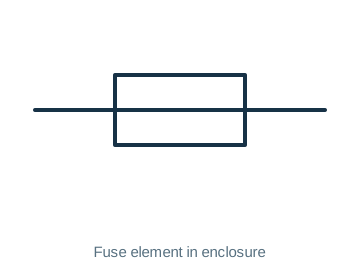 | 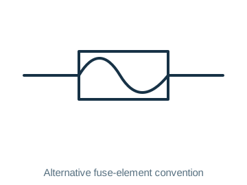 |
| Galvanometer | 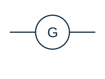 | 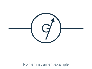 |
| Ground, Chassis, Earth | 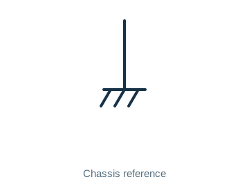 | 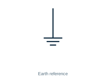 |
| Handset | 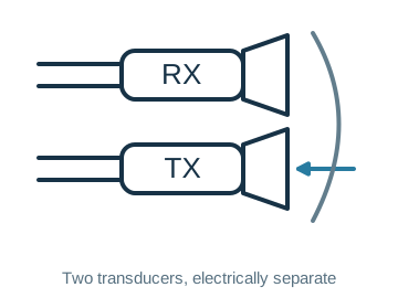 | |
| Headphone, Double | 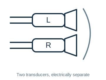 | |
| Headphone, Single | 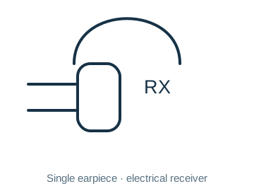 | |
| Inductor, Air-Core | 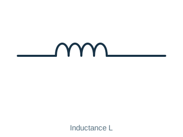 | |
| Inductor, Bifilar | 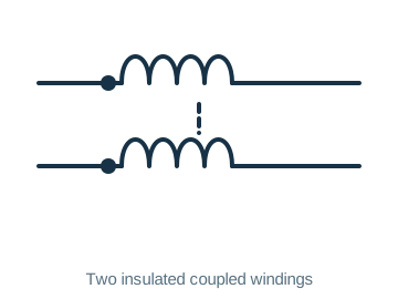 | |
| Inductor, Iron-Core | 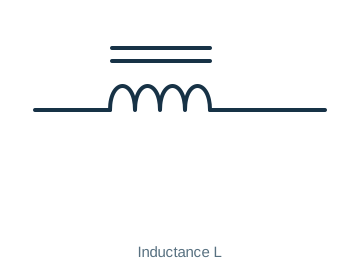 | |
| Inductor, Tapped | 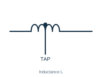 | |
| Inductor, Variable | 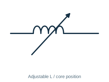 | 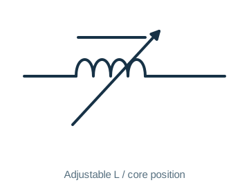 |
| Integrated Circuit | 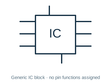 | |
| Inverter | 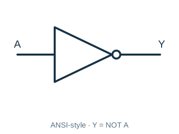 | |
| Jack, Coaxial | 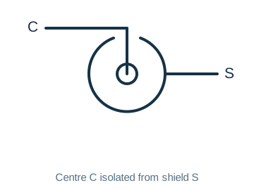 | |
| Jack, Phone, 2-Conductor | 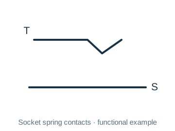 | |
| Jack, Phone, 2-Conductor Interrupting | 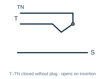 | |
| Jack, Phone, 3-Conductor | 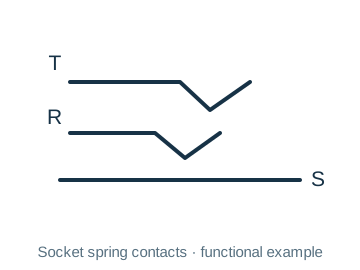 | |
| Jack, Phono | 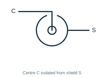 | |
| Key, Telegraph | 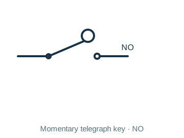 | |
| Lamp, Incandescent | 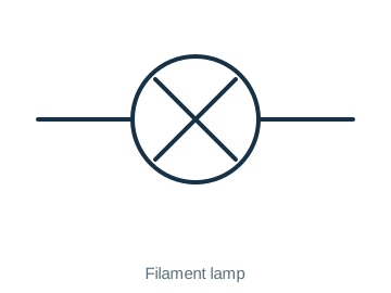 | |
| Lamp, Neon | 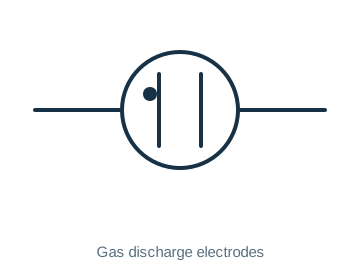 | |
| Male Contact, General | 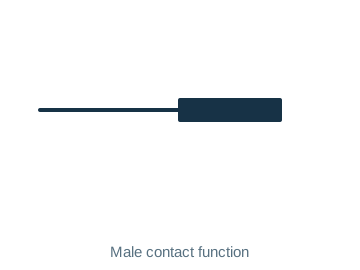 | |
| Microphone | 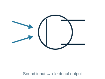 | |
| Nand Gate | 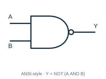 | |
| Negative Voltage Connection | 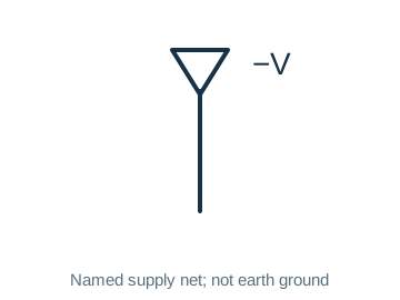 | |
| Nor Gate | 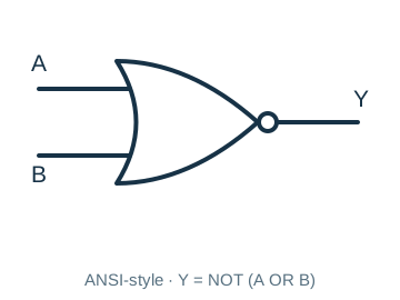 | |
| Operational Amplifier | 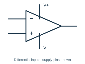 | |
| Or Gate | 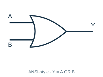 | |
| Photocell, Tube | 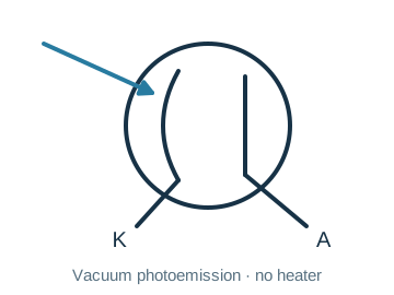 | |
| Plug, Phone, 2-Conductor | 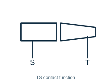 | |
| Plug, Phone, 3-Conductor | 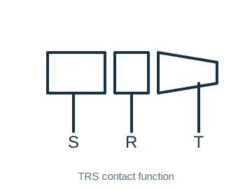 | |
| Plug, Phono | 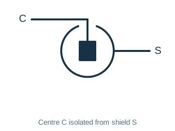 | |
| Positive Voltage Connection | 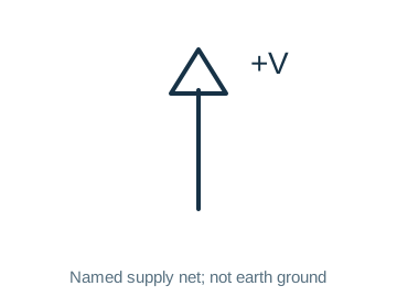 | |
| Potentiometer, Rheostat | 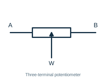 | 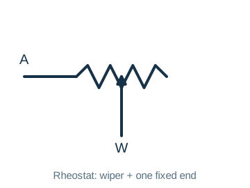 |
| Probe, Radio-Frequency | 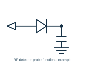 | |
| Rectifier, Semiconductor | 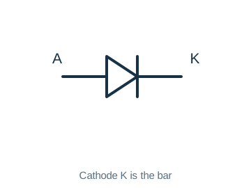 | |
| Rectifier, Silicon-Controlled | 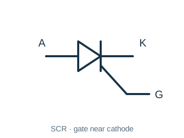 | |
| Rectifier, Tube-Type | 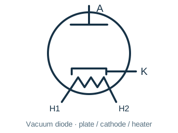 | |
| Relay, DPDT | 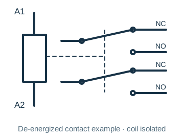 | |
| Relay, DPST | 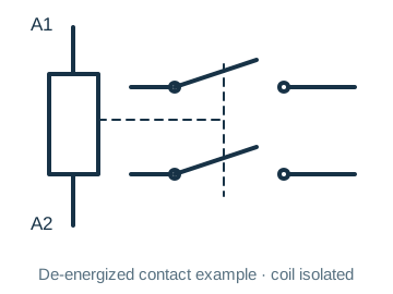 | |
| Relay, SPDT | 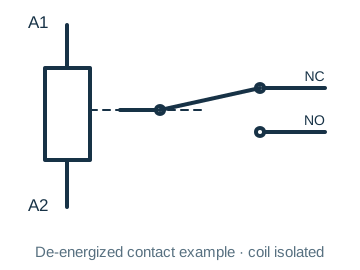 | |
| Relay, SPST | 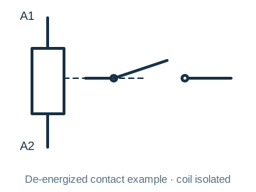 | |
| Resistor | 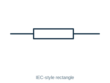 | 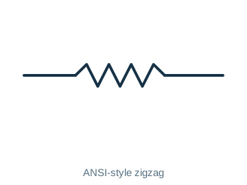 |
| Resonator | 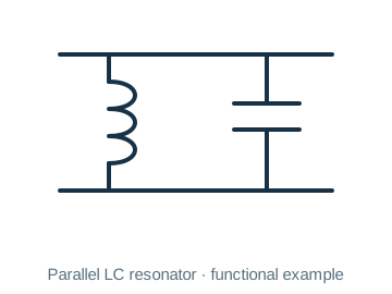 | |
| RTD | 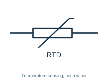 | Source reused a rheostat graphic; this is not an RTD symbolLegacy record: “”. The same cs_potentiometer2 image is used in the potentiometer/rheostat row. Its occurrence is retained with an explicit mismatch notice; use this row’s first image for RTD. |
| Saturable Reactor | 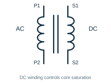 | |
| Shielding | 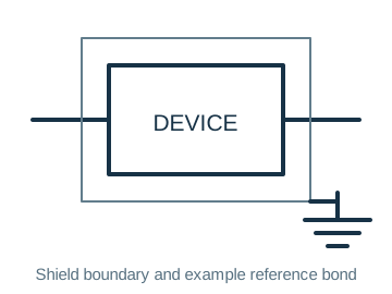 | |
| Signal Generator | 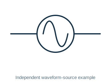 | |
| Speaker | 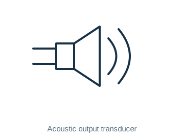 | 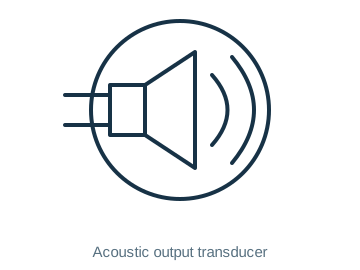 |
| Switch, DPDT | 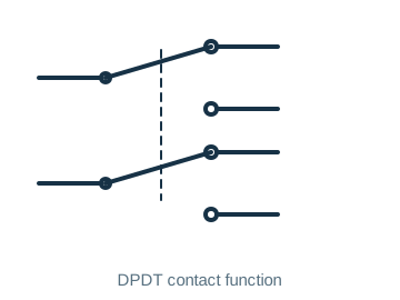 | |
| Switch, DPST | 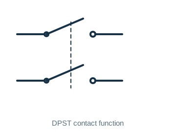 | |
| Switch, Momentary-Contact | 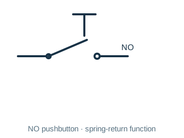 | |
| Switch, Rotary | 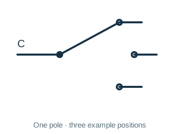 | |
| Switch, SPDT | 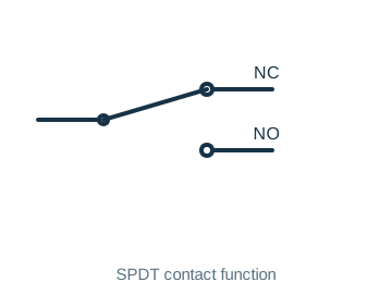 | |
| Switch, SPST | 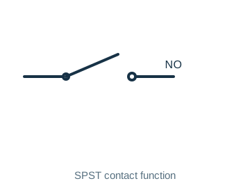 | |
| Terminals, General, Balanced | 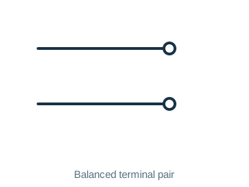 | |
| Terminals, General, Unbalanced | 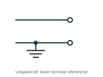 | |
| Test Point | 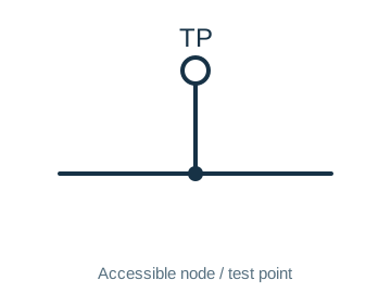 | |
| Thermistor | 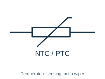 | |
| Thermocouple | 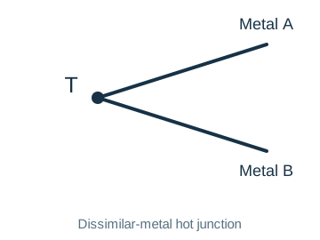 | 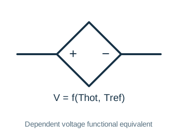 |
| Thyristor, SCR | 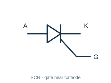 | |
| Thyristor, TRIAC | 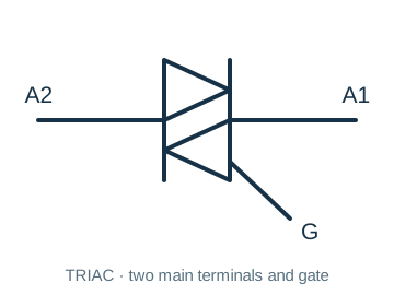 | |
| Transformer, Air-Core | 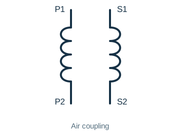 | |
| Transformer, Iron-Core | 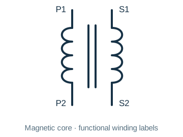 | |
| Transformer, Tapped Primary | 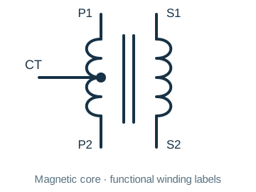 | |
| Transformer, Tapped Secondary | 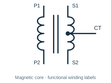 | |
| Transistor, Bipolar, npn | 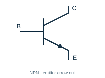 | |
| Transistor, Bipolar, pnp | 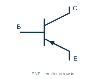 | |
| Transistor, Field-Effect, N-Channel | 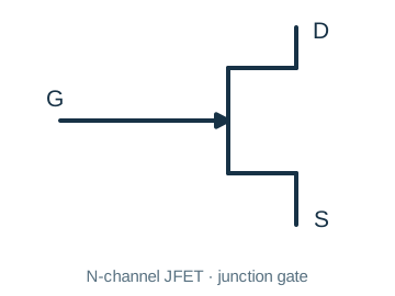 | |
| Transistor, Field-Effect, P-Channel | 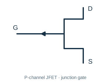 | |
| Transistor, Metal-Oxide, Dual-Gate | 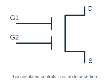 | |
| Transistor, Metal-Oxide, Single-Gate | 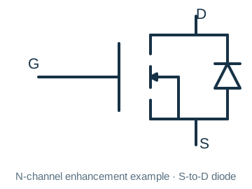 | |
| Transistor, Photosensitive | 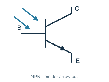 | |
| Transistor, Unijunction | 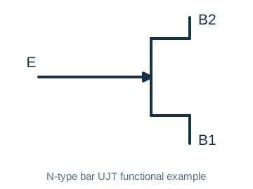 | |
| Tube, Diode | 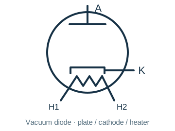 | |
| Tube, Pentode | 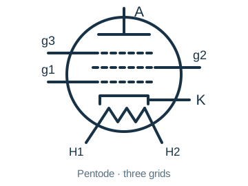 | |
| Tube, Photomultiplier | 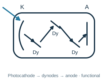 | |
| Tube, Tetrode | 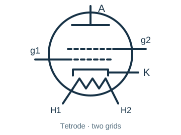 | |
| Tube, Triode | 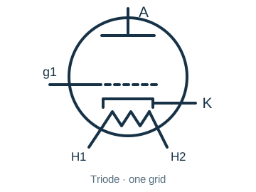 | |
| Unspecified Component | 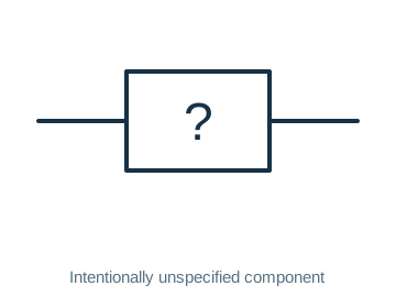 | |
| Voltmeter | 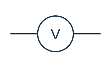 | |
| Wattmeter | 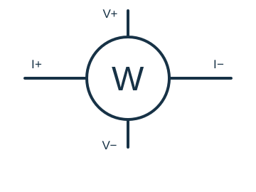 | 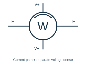 |
| Wires | 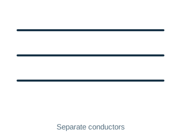 | |
| Wires, Connected, Crossing | 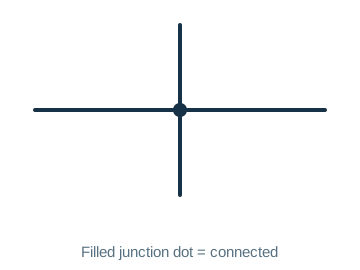 | 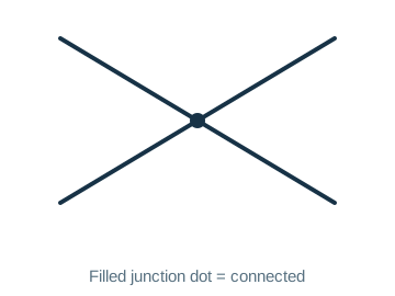 |
| Wires, Not Connected, Crossing | 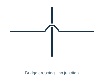 | 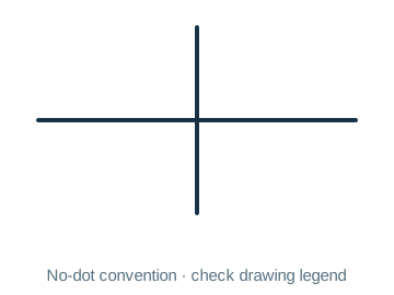 |
Frequently asked questions
Why do resistors use both rectangular and zigzag shapes?
They reflect common drawing traditions, labeled IEC-style and ANSI-style here. Interpret them with the R reference, value and two connections; drawing style does not determine material, tolerance or rating.
Can one arrow mnemonic cover BJTs and JFETs?
No. BJT arrows are on E: NPN points out and PNP in. JFET arrows mark the gate junction: N-channel points toward the channel and P-channel away. Identify device type and terminals first.
Can continuous and broken MOSFET channels be ignored?
No. Common detailed symbols use a broken channel for enhancement and a continuous channel for depletion, while simplified symbols may omit that distinction. Check body connection, S/D and body-diode direction as well.
How do independent and dependent sources differ?
Common notation uses a circle for independent voltage/current sources and a diamond for dependent sources; +/− or an arrow distinguishes voltage from current. The thermocouple functional equivalent shows a temperature-difference-controlled voltage, not a fixed-voltage battery.
Does this table include every flip-flop symbol?
No. The source includes basic logic gates, not a complete set of flip-flops. For a flip-flop check D/JK/SR type, the clock triangle, active edge and asynchronous set/reset polarities.
Does a crossing without a dot always mean no connection?
Check the convention used by the whole drawing. This page labels junction dots, wire bridges and no-dot examples explicitly. Use net names, nodes and the drawing legend before wiring.
Are chassis, earth and signal ground the same node?
Not necessarily. Chassis denotes the enclosure/frame reference, earth denotes an earth reference, and signal ground is the circuit’s chosen potential reference. Connections between them require the equipment schematic and grounding design; none of these graphics proves a completed protective-earth connection.
Related tools and references
Sources and verification
- IEC: 60617 graphical-symbol database and scope
- Toshiba: NPN/PNP bipolar transistors
- onsemi: N-channel JFET gate arrow and terminals
- Nexperia: MOSFET channels, body and body diode
- STMicroelectronics: TRIAC A1/A2/G terminals
- Texas Instruments: NAND logic and inverted output
- Hamamatsu: photocathode, dynodes and anode
- STMicroelectronics: SCR A/K/G terminals
- TE Connectivity: relay poles, throws and contact forms
- JJ Electronic: pentode anode, three grids, cathode and heater
- Microchip: thermocouple temperature difference and voltage
- Original research: Gunn effect and negative differential resistance
- Skyworks: varactor reverse bias and junction capacitance
- STMicroelectronics: N-channel power-MOSFET body diode
Legacy baseline: the Electrodoc Pro 5.2 data package. Raw records are retained and checked factual corrections are shown explicitly.